Process and apparatus for removing residues from the microstructure of an object
- Summary
- Abstract
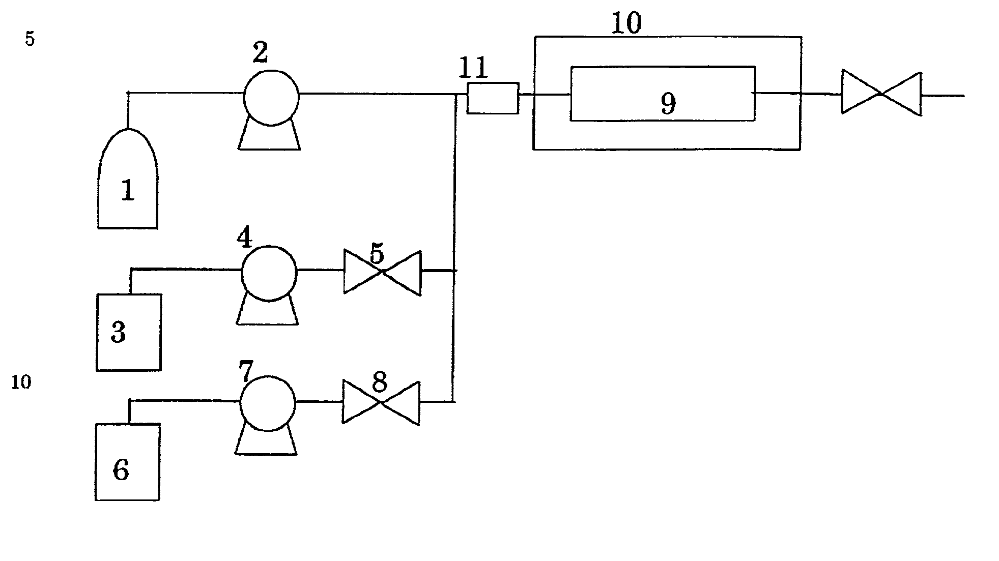
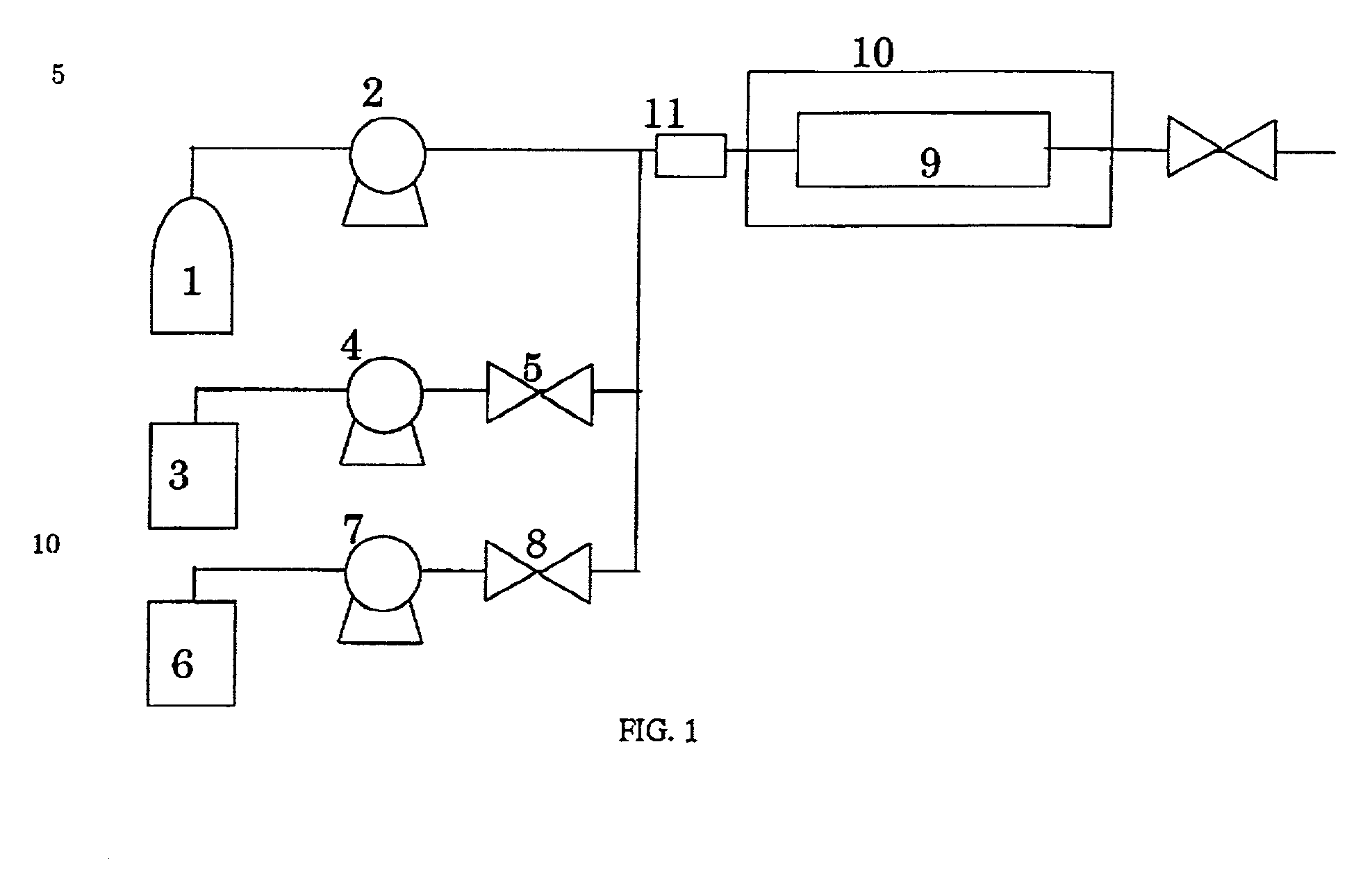
- Description
- Claims
- Application Information
AI Technical Summary
Benefits of technology
Problems solved by technology
Method used
Image

Examples
experiment 1
[0031] This experiment is carried out by dipping an object in an additive shown in table 1 at an atmospheric pressure at a temperature in the range of from 40.degree. C. to 100.degree. C. for 20 minutes. The object for this experiment is a silicon wafer having a SiO2 layer coated with a novolac phenol type resist, patterned by a development, and treated to form microstructures on its surface by dry etching of a fluorine gas. A rate of removing residues is estimated as a ratio of an area of the surface adhering with residues after removing and before removing by a microscope. The term "x" and the term ".largecircle." mean that the rate is less than 90%, and 90% or more, respectively. The term ".O slashed." means the rate is 90% or more when the additive is diluted ten times by a co-solvent such as dimethylsulfoxide.
[0032] The results are summarized in table 1.
1 TABLE 1 Additive Removability Acetone x Dimethylformamide x Dimethylsulfoxide x N-methyl-2-pyroridon x Propylencarbonate x M...
experiment 2
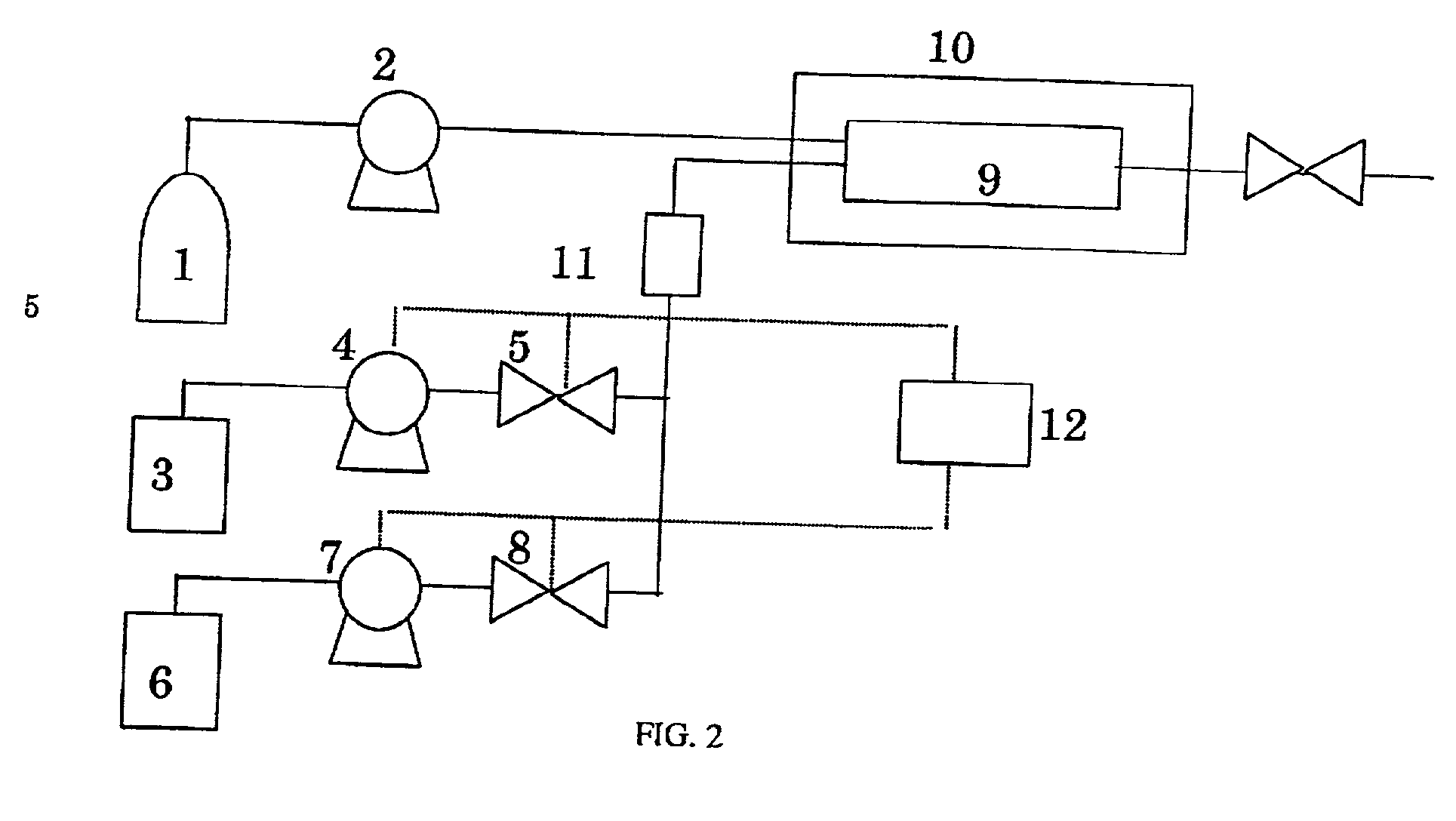
[0034] This experiment for investigating an effect of co-solvent on a solubility of additive in CO.sub.2 is carried out via the apparatus shown in FIG. 5. CO.sub.2 is introduced into the vessel 9 from the CO.sub.2 cylinder 1 by the pump 2. The pressure and the temperature in the vessel are maintained at 20 MPa and 80.degree. C. by the thermostat 10. The additive and co-solvent are mixed in the ratio shown in table 2, then the mixture is introduced into the vessel 9 from the mixing tank 14 by the pump 4. The same amount of CO.sub.2 as the mixture is evacuated from the vessel 9 so that the pressure is maintained at 20 MPa when the mixture is introduced. The effect of co-solvent, i.e., whether the additive is dissolved in CO.sub.2, is observed through the glass window 13 of the vessel 9. When the additive is not dissolved in CO.sub.2, two phases are observed through the window. The term "x" in table 2 means that the two phases are observed. The term ".largecircle." means the co-solvent...
experiment 3
[0036] This experiment for removing residues using a remover including high pressure CO.sub.2, additive(s), and co-solvent(s) is carried out via the apparatus of FIG. 1. The object in this experiment is the same as the one in the experiment 1. The kind and concentration of the additive and co-solvent in the remover are shown in table 3. The terms ".O slashed.", ".largecircle." and "x" in table 3 indicate the rate of removing residues being 90% or more, 60% or more, and 10% or less, respectively.
3TABLE 3 Exp. No. Additive Wt % Co-solvent Wt % Rate 3-1 Choline 0.05 Ethanol 20.0 O 3-2 Choline 1.70 Ethanol 35.3 .O slashed. 3-3 TMAH 1.21 Methanol 22.2 .O slashed. 3-4 TMAH 1.50 Dimethylsulfoxide 30.0 .O slashed. 3-5 Non Non X 3-6 Non Ethanol 20.0 X 3-7 Non dimethylsulfoxide 30.0 X
[0037] As shown in table 3, in the experiment No. 3-1.about.3-4, the residues are effectively removed.
PUM
 Abstract
Description
Claims
Application Information
 - Generate Ideas
- Intellectual Property
- Life Sciences
- Materials
- Tech Scout
- Unparalleled Data Quality
- Higher Quality Content
- 60% Fewer Hallucinations
Browse by: Latest US Patents, China's latest patents, Technical Efficacy Thesaurus, Application Domain, Technology Topic, Popular Technical Reports.
© 2025 PatSnap. All rights reserved.Legal|Privacy policy|Modern Slavery Act Transparency Statement|Sitemap|About US| Contact US: help@patsnap.com