Insulated electric power cable

a technology of electric power cable and insulating cable, which is applied in the direction of pipes, closure stoppers, packaging, etc., can solve the problems of reducing impulse breakdown strength, reducing breakdown voltage, and modification failing to give a satisfactory property to direct-current breakdown strength

Inactive Publication Date: 2002-11-28
FURUKAWA ELECTRIC CO LTD
View PDF0 Cites 31 Cited by
  • Summary
  • Abstract
  • Description
  • Claims
  • Application Information

AI Technical Summary

Benefits of technology

0025] The insulated electric power cable of the present invention can be preferably used as a high voltage direct-current power-transmission cable, since the cross-linkable resin composition that forms the

Problems solved by technology

Consequentially, the problem arises that the breakdown voltage considerably decreases.
However, if a filler, such as carbon black or magnesium oxide, is added to the conventional electrically insulating resin composition, another problem arises: the imp

Method used


Image

  • Insulated electric power cable
  • Insulated electric power cable

Examples


examples 1 to 3

[0027] To pellets of low density polyethylene (manufactured by Mitsubishi Chemical Corporation, Density=0.92 g / cm.sup.3, MI=1.0 g / 10 miN, hereinafter abbreviated as "LDPE"), an organic peroxide cross-linking agent, N,N'-(4,4'-diphenylmethane)bismaleimide and an anti-aging agent were added in the proportion as shown in Table 1, and thoroughly mixed with stirring by means of a blender. The resulting mixture was supplied for the production of the electric power cable.

[0028] On the conductor having a section of 200 mm.sup.2, a 1-mm thickness internal semi-conductive layer composed of ethylene / vinyl acetate copolymer (a cross-linking agent, carbon black, an antioxidant), a 3.5-mm thickness insulating layer composed of the cross-linkable resin composition shown in the above Table 1, and further thereon a 0.7-mm thickness external semi-conductive layer composed of the same materials as the internal semi-conductive layer were formed by simultaneous extrusion and coating method to prepare a ...

examples 4 to 7

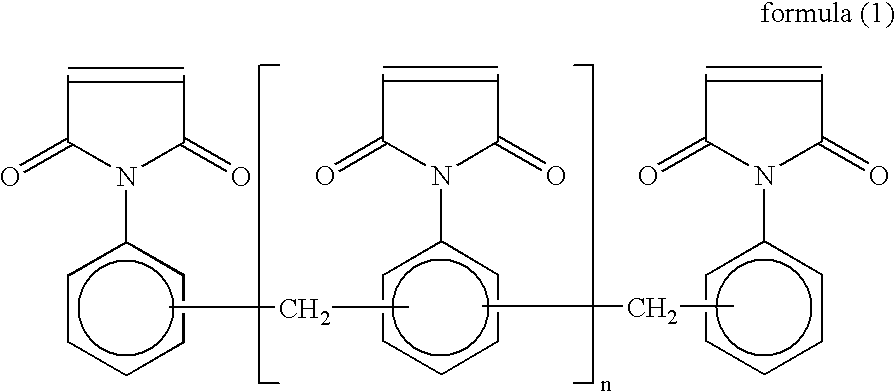
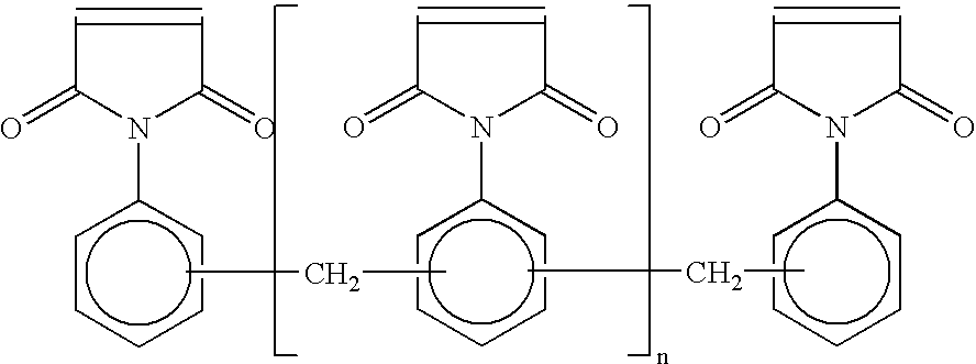
[0031] The resin compositions, in which bis(3-ethyl-5-methyl-4-maleimidoph-enyl)methane, 2,2-bis[4-(4-maleimidophenoxy)phenyl]propane, N,N'-m-phenylenebismaleimide, or the compound represented by formula (1), and other additives were blended with the low density polyethylene in the same manner as in the foregoing Examples 1 to 3, except for the proportion, as shown in Table 2, were supplied for the production of the electric power cables, respectively.

examples 8 to 11

[0032] The resin compositions, in which dicumyl peroxide, t-butyl cumyl peroxide, or 1,3-bis(t-butylperoxy isopropyl)benzene as the organic peroxide cross-linking agent, 2,4-diphenyl-4-methyl-1-pentene as the anti-scorching agent, and other additives were blended with the low density polyethylene in the same manner as in the foregoing Examples 1 to 3, except for the proportion, as shown in Table 2, were supplied for the production of the electric power cables, respectively.

[0033] (Test)

[0034] With respect to the thus-obtained electric power cables, the following evaluations (1), (2), (3) and (4) were conducted. The results which were obtained are shown in Tables 4 to 6.

[0035] (1) Direct-Current Breakdown Property

[0036] An electric power cable having an effective length of 8 m was prepared. While sending an electric current to the cable so that the conductor temperature becomes 90.degree. C., the starting voltage was set -60 kV and then the voltage was increased by a step-up of -20 k...


PUM

PropertyMeasurementUnit
Percent by massaaaaaaaaaa
Angleaaaaaaaaaa

Abstract

An insulated electric power cable having an insulator layer formed by extrusion-coating and cross-linking a cross-linkable resin composition, which contains a polyolefin blended with a total of 0.05 to 0.4 parts by mass of at least one compound selected from the group of compounds such as N,N'-(4,4'-diphenylmethane)bismaleimide, based on 100 parts by mass of the polyolefin, and a prescribed amount of an organic peroxide cross-linking agent.

Description

[0001] This is a continuation of PCT Application PCT / JP01 / 06408, filed Jul. 25, 2001. The prior PCT application was not published in English under PCT Article 21(2).[0002] The present invention relates to an insulated electric power cable.[0003] Among plastic insulated electric power cables, a cross-linked polyethylene insulated electric power cable, having an insulating layer composed of a cross-linked polyethylene, has various advantages of not only excellent electrical property, mechanical property, and heat-resistance property, but also easy maintenance. Because of these advantages, the cross-linked polyethylene insulated electric power cable is the mainstream type of power-transmission cable. Generally, an insulator layer of the cross-linked polyethylene insulated electric power cable is formed by a method that comprises steps of; extrusion-coating, on a conductor, a cross-linkable resin composition, composed of a low density polyethylene blended with a cross-linking agent, an ...

Claims


Application Information

Patent Timeline
IPC IPC(8): C08K5/14C08K5/3415C08K5/3417C08L23/02H01B3/30H01B3/44
CPCC08K5/14Y10T428/1393C08K5/3417C08L23/02C08L2203/202H01B3/306H01B3/442C08K5/3415Y10T428/1386
Inventor SAKURAI, TAKAHIROTANAKA, TOSHIYA
Owner FURUKAWA ELECTRIC CO LTD
Why Eureka
Try Eureka