Conductive plastic compositions and method of manufacture thereof

a technology of conductive plastics and compositions, which is applied in the direction of transportation and packaging, special tyres, and non-conductive materials with dispersed conductive materials, etc. it can solve the problems of impact and surface finish of composite materials, less cost effective, and carbon fibers having diameters greater than 3 micrometers, so as to reduce the concentration of carbon fibers and achieve the same surface resistivity , the effect of reducing the concentration

Inactive Publication Date: 2002-12-05
SABIC GLOBAL TECH BV
View PDF7 Cites 123 Cited by
  • Summary
  • Abstract
  • Description
  • Claims
  • Application Information

AI Technical Summary

Benefits of technology

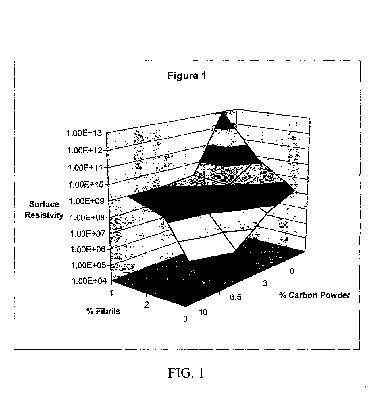
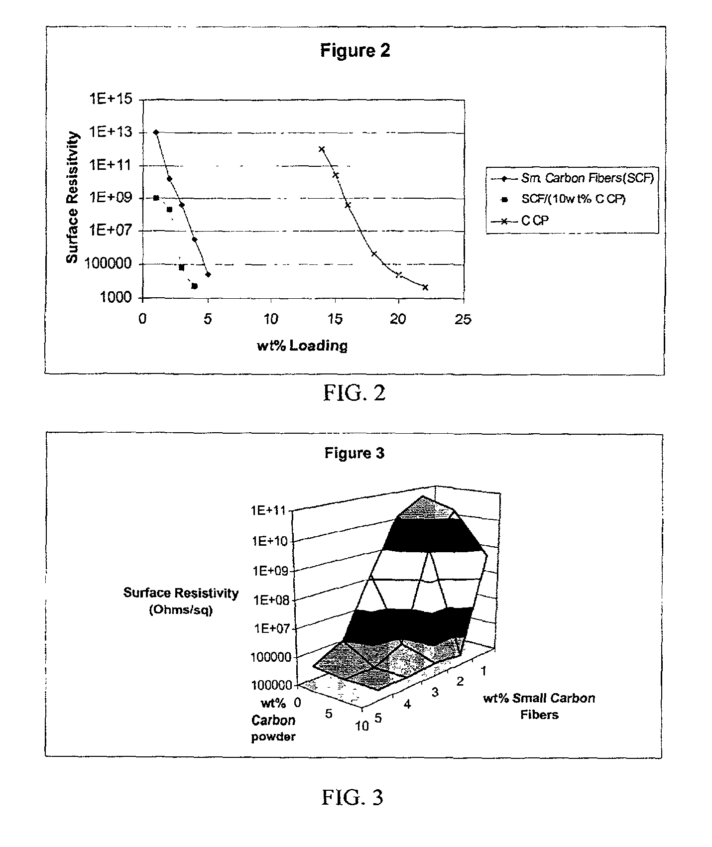
0031] For example, from FIG. 1 it can be seen that the addition of 3 wt % of carbon powder to polycarbonate resin containing 1 wt % small carbon fibers produces a surface resistivity similar to the polymeric resin containing only 2 wt % small carbon fibers. Similarly FIG. 2 shows that the addition of approximately about 5 wt % small carbon fibers (Sm. Carbon Fibers (SCF)) to polycarbonate resin produces a surface resistivity of 10.sup.5 ohm/square. A similar surface resistivity can be obtained when approximately about 18 wt % of carbon powder (C CP) alone is used. If however, about 3 wt % small carbon fibers are combined with about 10 wt % carbon powder in polycarbonate resin (SCF/(10 wt % C CP)), then the same surface resistivity is attainable. Thus, synergy between conductive components helps achieve the same surface resistivity while reducing their concentration.
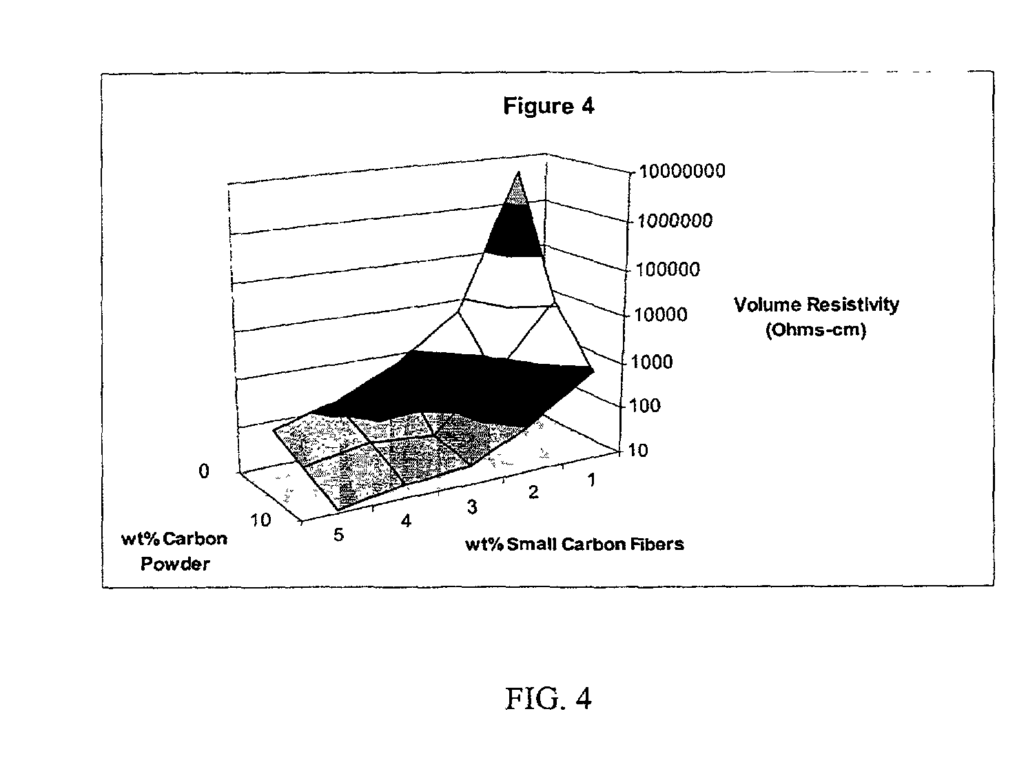
0032] FIGS. 3 and 4 demonstrate a similar synergy between small carbon fibers and carbon powder in polybutylene terephthalate resin that consequently improves both the surface and volume resistivity of the composition.
0033] Similarly when glass fib

Problems solved by technology

However, the incorporation of carbon fibers having diameters greater than about 3 micrometers is detrimental to other properties such as the impact and surface finish of the composite.
Metal powders and flakes greatly increase the specific gravity of polymeri

Method used


Image

  • Conductive plastic compositions and method of manufacture thereof
  • Conductive plastic compositions and method of manufacture thereof
  • Conductive plastic compositions and method of manufacture thereof

Examples


example 2

[0041] Lexan (polycarbonate) resin from GE Plastics was blended in a 30 mm twin screw Werner and Pfleiderer extruder with polycarbonate masterbatch containing VGCF obtained from Hyperion Catalysis International. The VGCF are present in an amount of about 15 wt % in the masterbatch. The Lexan along with the VGCF masterbatch are fed into the extruder through at the throat. The glass is fed into the extruder through a side feeder. The temperature of the die was set at 315.degree. C. The extrudate was immediately quenched in a water bath and pelletized. The pellets were dried in an oven and injection molded into 4 inch diameter discs of 0.125" thickness on a 120 ton VanDorn injection molding machine. The surface resistivity was obtained using the Keithley Electrometer, high resistivity meter 651 7A with the 8007 resistivity test fixture.

[0042] Table 2 shows measured surface resistivity for compositions 14-18, which contain no glass fibers, compositions 20-23, which contain 20 wt % / glass...


PUM

PropertyMeasurementUnit
Diameteraaaaaaaaaa
Fractionaaaaaaaaaa
Angleaaaaaaaaaa

Abstract

An improved, conductive, polymeric composition comprises a polymeric resin; an electrically conductive filler system comprising small carbon fibers and either carbon powder or fibrous non-conductive filler or a combination of both. The amount of the conductive filler system utilized is dependent upon the desired electrical conductivity (surface and volume conductivity or resistivity) while preferably preserving intrinsic properties of the polymeric resin such as impact, flex modulus, class A finish, and the like. The conductive articles made from these compositions can therefore be used for electromagnetic shielding, electrostatic dissipation or antistatic purposes in packaging, electronic components, housings for electronic components and automotive housings.

Description

[0001] This application claims the benefit of U.S. Provisional Application Serial No. 60 / 287,127 filed Apr. 27, 2001.BACKGROUND OF INVENTION[0002] Plastic (polymeric resin) is often the material of choice for components in electronic products such as computers, photocopiers, and the like because it offers design flexibility, cost-effective manufacturing, and light weight products. In order to function efficiently in such applications, normally insulating polymeric resin must be made electrically conductive to provide electromagnetic shielding, electrostatic dissipation or antistatic properties to such components.[0003] Polymeric resins are typically made conductive by incorporating electrically conductive fillers such as carbon fibers, metal powders or flakes, vapor grown carbon fibers, carbon nanotubes, carbon black, and the like. However, the incorporation of carbon fibers having diameters greater than about 3 micrometers is detrimental to other properties such as the impact and s...

Claims


Application Information

Patent Timeline
IPC IPC(8): C08K5/00H01B1/24
CPCH01B1/24C08K5/00
Inventor AMARASEKERA, JAYANTHABALFOUR, KIMLIETZAU, CHRISTIAN
Owner SABIC GLOBAL TECH BV
Why Eureka
Try Eureka