Coated cutting tool

a cutting tool and coating technology, applied in the direction of shaping cutters, manufacturing tools, natural mineral layered products, etc., can solve the problems of surface roughness deterioration and substrate damage of machined workpieces, and achieve high hardness and abrasion resistance, prevent damage from aluminum oxide of outer layers, and high wear resistance

Inactive Publication Date: 2002-12-12
SUMITOMO ELECTRIC IND LTD
View PDF1 Cites 71 Cited by
  • Summary
  • Abstract
  • Description
  • Claims
  • Application Information

AI Technical Summary

Benefits of technology

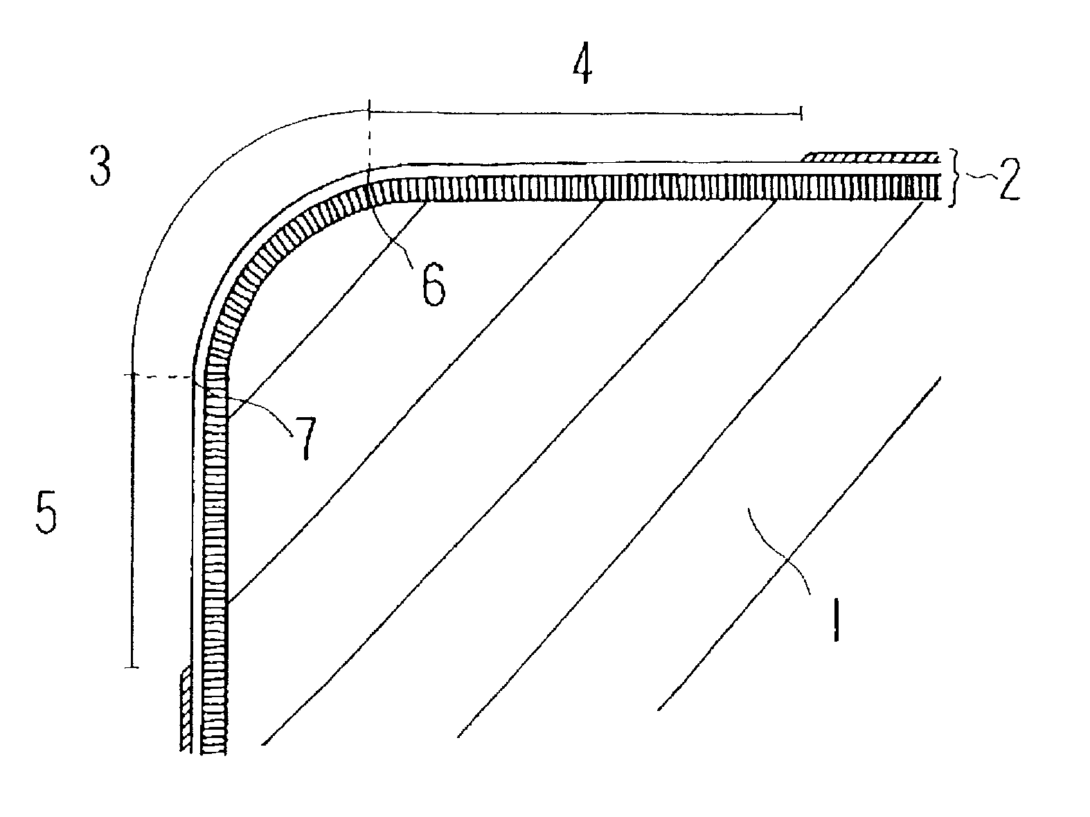
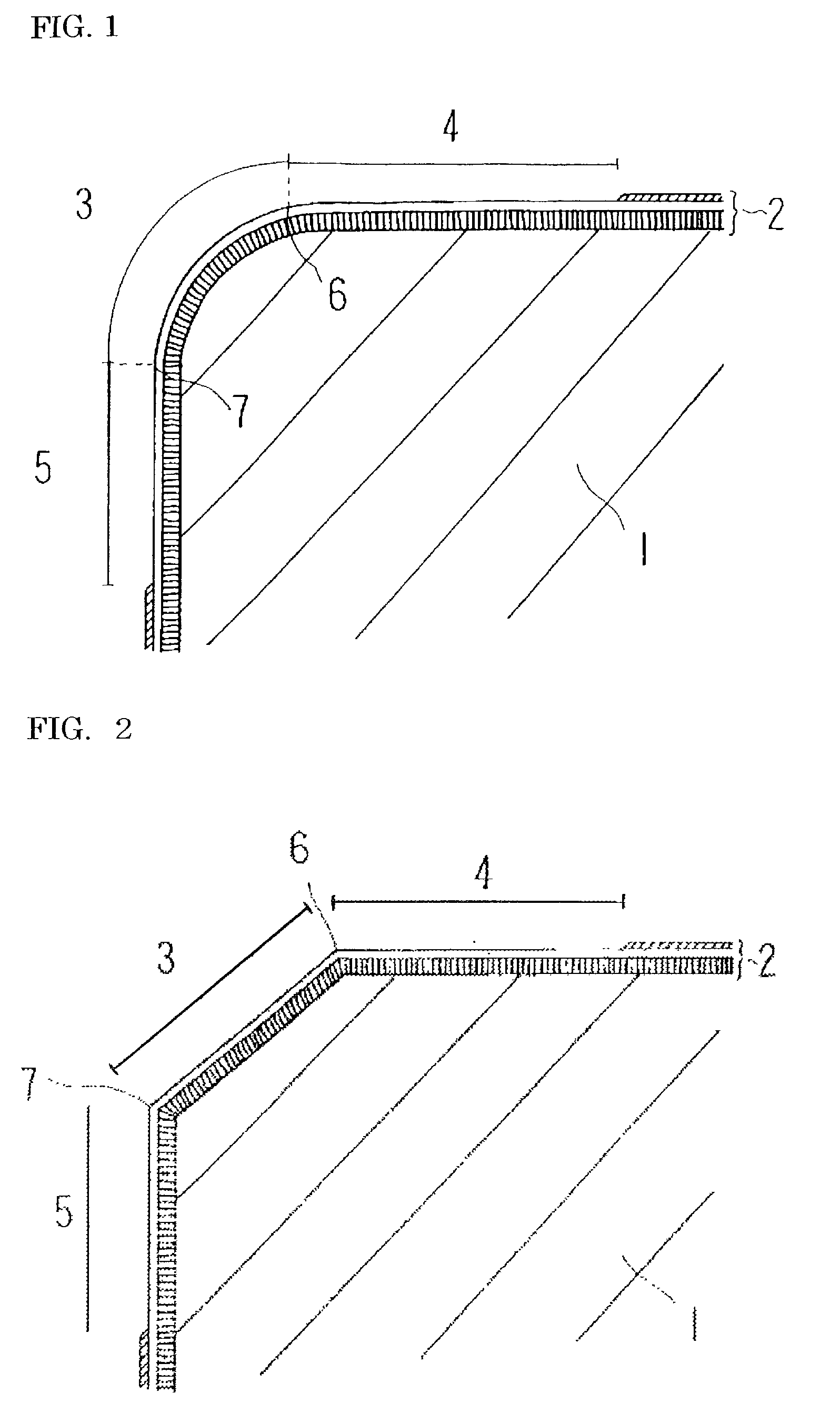
[0012] Therefore, the hard coating layer at the blade-edge ridge, a range of at least 200 .mu.m from the rake face side boundary of the same blade-edge ridge toward the rake face side, and a range of at least 50 .mu.m from the flank side boundary of the same blade-edge ridge toward the flank side is formed to be substantially 0.2 .mu.m or less in surface roughness (Rmax) (the reference length is set to 5 .mu.m), whereby such welding and adhesion of a workpiece and such transferring onto the workpiece are prevented. Thus, the tool life can be improved by increasing fracture resistance and wear resistance simultaneously, and the surface roughness of a machined workpiece can also be improved. Particularly, this effect is more remarkable in the case of dry cutting. It is desirable that the hard coating layer comprises one or more kinds of substances selected from the group consisting of carbides, carbonitrides, borides, and oxides of one or more kinds of metal elements selected from the periodic table IVa, Va, and Via groups, Al, and Si, and the solid solutions thereof.
[0014] If the invention is applied to a non-ground type tool in which the flank of the substrate has an as-sintered surface, the effect of the present invention is more remarkable. Recently, for reducing manufacturing costs, non-ground type tools have widely diffused, in which the tool flank side has an as-sintered surface. In this case, tool surface unevenness may be transferred onto a workpiece, or welding and adhesion occur, resulting in abnormal wear and deterioration in surface roughness of the workpiece. Application of the present invention to such case therefore produces more remarkable effects.
[0020] The inner layer comprises one or more layers of Ti (CwBxNyOz) (herein, w+x+y+z=1, w, x, y, z>0) which is high in hardness and abrasion resistance, by which high wear resistance can be obtained. Particularly, in a case where titanium carbonitride having a film thickness of 2-20 .mu.m and a columnar crystal structure is disposed in the inner layer, wear resistance and chipping resistance can be simultaneously realized, and damage from the aluminum oxide of the outer layer can be prevented in intermittent cutting or cutting for machining parts. In addition, high wear resistance can be obtained while preventing destruction of the film of the inner layer, by which tool performance can be significantly improved. If the film thickness of titanium carbonitride is less than 2 .mu.m, wear resistance is insufficient, and if the thickness exceeds 20 .mu.m, the strength of the coating layer decreases.
[0021] Furthermore, when an innermost layer contacting with the substrate comprises a titanium nitride film of 0.2-3 .mu.m in thickness having a granular structure, tool performance can be further improved by improving the adhesive force between the inner layer and the substrate. If this film thickness is less than 0.2 .mu.m, the effect for improving adhesive force of the film is insufficient, and if the thickness exceeds 3 .mu.m, wear resistance lowers.
[0031] The blade-edge ridge 3 includes an edge-honing portion for preventing blade-edge chipping. Round-honing (FIG. 1) and chamfer-honing (FIG. 2) may be employed as edge-honing.

Problems solved by technology

When cutting a workpiece of ductile cast iron, stainless steel, Inconel, or the like, which easily welds and adheres, in a range of 200 .mu.L m from the rake face side boundary of the blade-edge ridge toward the rake face side, chips weld and adhere to the coating layer, and when the adhered matter comes off, the coating layer also spalls, resulting in damage to the substrate.
Also in a range of at least 50 .mu.m from the flank side boundary of the same blade-edge ridge toward the flank side, chips weld and adhere due to micro-chipping of the coating layer and abnormal wearing progresses, or the surface unevenness of the coating layer and adhered matter on the surface are transferred onto the workpiece, resulting in deterioration in surface roughness of the machined workpiece.

Method used


Image

  • Coated cutting tool
  • Coated cutting tool

Examples


experimental example 2

[0045] Cutting tips with a form of model No. CNMG120408 were manufactured from a sintered hard alloy with a composition of 88% WC-3% ZrCN-4% TaNbC-5% Co (%: % by weight). Next, for edge machining to prepare substrates, the whole of the cutting blade portion was subjected to honing in a width of 0.05 mm viewed from the rake face side. The flank of this substrate is a sintered surface.

[0046] Cutting tip samples were manufactured by coating the surface of these substrates with TiN, TiC, TiCN, ZrCN, Al.sub.2O.sub.3, and others by means of normal chemical vapor deposition (CVD). Next, the blade-edge ridge and the rake face side and flank side from the same ridge were subjected to grinding and lapping by using an elastic grindstone, and then the surface roughness (Rmax) with respect to a reference length of 5 .mu.m was measured from a scanning electron microscope photograph of the cross-section of the tips. The results of the measurement are shown in Table II.

[0047] By using the cutting t...

experimental example 3

[0057] Cutting tips with a form of model No. SDKN1203 were manufactured from a sintered hard alloy with a composition of 81% WC-5% TiCN-4% TaNbC-10% Co (%: % by weight). Next, for edge machining to prepare substrates, the whole of the cutting blade portion was subjected to chamfer-honing in a width of 0.10 mm viewed from the rake face side. The surface of the substrates partially includes an as-sintered surface and a ground surface.

[0058] Cutting tip samples were manufactured by coating the surface of the substrates with TiN, TiC, TiCN, TiAlN, Al.sub.2O.sub.3, and others by normal chemical vapor deposition (CVD) and physical vapor deposition (PVD)(herein, arc ion plating). Next, at the blade-edge ridge, rake face side and flank side, grinding and lapping were applied by using a brush, and then the surface roughness (Rmax) with respect to the reference length of 5 .mu.m was measured from a scanning electron microscope photograph of the cross-section of the tips. The results of the me...

experimental example 4

[0068] Cutting tips with a form of model No. CNMG120408 were manufactured from a cermet alloy with a composition of 12% WC-65% TiCN-6% TaNbC-3% MO2C-7% Co-7% Ni (%: % by weight). Then, for edge machining to prepare substrates, the whole of the cutting blade portion was subjected to honing in a width of 0.06 mm viewed from the rake face side. The flank of the substrates has an as-sintered surface.

[0069] Cutting tip samples were manufactured by coating the surface of the substrates with TiN, TiC, TiCN, TiAlN, Al.sub.2O.sub.3, and others by normal chemical vapor deposition (CVD) and physical vapor deposition (PVD)(herein, arc ion plating). Next, at the blade-edge ridge, rake face side, and flank side, grinding and lapping were applied by using an elastic grindstone, and then surface roughness (Rmax) with respect to the reference length of 5 .mu.m was measured from a scanning electron microscope photograph of the cross-section of the tips. The results of the measurement are shown in Tab...


PUM

PropertyMeasurementUnit
lengthaaaaaaaaaa
lengthaaaaaaaaaa
lengthaaaaaaaaaa

Abstract

The present invention provides a coated cutting tool in which fracture resistance and wear resistance are simultaneously realized, tool life is improved, and surface roughness of machined workpiece is improved The coated cutting tool is provided with hard coating layer 2 on substrate 1. The substrate 1 is formed of a binder phase comprising one or more kinds of iron-group metals and a hard phase comprising one or more kinds of substances selected from the group consisting of carbides, nitrides, and oxides of the periodic table IVa-, Va-, and VIa-group elements, and solid solutions thereof. In the coating layer 2, blade-edge ridge 3, a range of at least 200 mum from the rake face side boundary 6 of the same ridge toward the rake face side, and a range of at least 50 mum from the flank side boundary 7 of the same ridge toward the flank side are formed to be smooth surfaces which substantially have surface roughness (Rmax) of 0.2 mum or less (reference length: 5 mum).

Description

[0001] The present invention relates to a coated cutting tool in which a hard coating layer having excellent wear resistance is formed[0002] There have been attempts to improve fracture resistance and wear resistance of super hard alloy cutting tools and lengthen the life of tools by depositing a coating layer of titanium carbide, titanium nitride, titanium carbonitride, aluminum oxide, or the like on the surface of a WC-group sintered hard alloy or cermet substrate.[0003] When cutting is carried out, particularly, when a workpiece which easily welds is cut by using these coated cutting tools, problems have frequently occurred in which the coating layer spalls away due to such welding and adhesion, and furthermore, fracturing of the substrate progresses, resulting in a decrease in the life of the tools.[0004] In order to solve these problems, Japanese Patent Nos. 2105396 and 2825693 disclose a technique for suppressing welding and adhesion of a workpiece and enhancing wear resistanc...

Claims


Application Information

Patent Timeline
Patent Type & Authority Applications(United States)
IPC IPC(8): C23C30/00
CPCC23C30/005Y10T428/265Y10T407/27Y10T428/24975Y10T428/24628B23B27/14
Inventor YAMAGATA, KAZUOIKEGAYA, AKIHIKO
Owner SUMITOMO ELECTRIC IND LTD
Why Eureka
Try Eureka