
Fabric coating containing energy absorbing phase change material and method of manufacturing same

a phase change material and fabric coating technology, applied in the field of fabric coatings, can solve the problems of unsatisfactory use of phase change material microspheres in thermoplastic gravure printing techniques, inability to achieve uniform dispersion of microspheres in the binder, and inability to apply phase change material binder binder to commercial coating equipmen

Inactive Publication Date: 2002-12-19
OUTLAST TECH LLC
View PDF0 Cites 32 Cited by
  • Summary
  • Abstract
  • Description
  • Claims
  • Application Information

AI Technical Summary

Benefits of technology

[0018] It is the principal object of the present invention to provide an improved fabric coating composition containing phase change material of a density sufficient to effect or control heat and energy transfer across the coating and / or store heat in the coating.
[0019] It is another object of the present invention to provide a coating composition of the foregoing character which will maintain substantially all of the breathability, flexibility or other principal qualities of the fabric to which it is applied.
[0021] It is a still further object of the present invention to provide coated fabrics having the aforementioned qualities which are durable, resistant to heat, moisture, solvents, laundering, and / or dry cleaning, without degradation to or loss of the phase change material.
[0022] It is still another object of the present invention to provide an improved method of applying coating compositions containing phase change materials and having the aforementioned qualities as coatings on fabrics by utilizing commercially available equipment.
[0023] It is yet another object of the present invention to provide an improved method of applying coatings containing phase change materials to fabrics without damage or degradation to the phase change materials.
[0024] It is still another object of the present invention to provide an improved method for evenly dispersing phase change material throughout a binder and maintaining an even distribution of the phase change material while coating a fabric with the binder and phase change material dispersion.

Problems solved by technology

Research has demonstrated that applying a binder containing microspheres of phase change materials with commercial coating equipment can be problematic.
For example, use of solvent based gravure printing techniques in which a solvent system was employed to achieve uniform dispersion of the microspheres in a binder proved unsuccessful because the solvent systems damaged the microspheres.
Thermoplastic gravure printing techniques also proved unsatisfactory for use with microspheres of phase change material.
When using higher temperature thermoplastic gravure printing techniques, sustained temperature of 325.degree. F. caused severe damage to the microspheres.
Although lower temperature thermoplastic gravure printing techniques avoided significant damage to the microspheres, the resulting coating was found lacking in washability and durability.
Moreover, lower temperature thermoplastic gravure printing techniques precluded addition of the desired amounts of the microspheres, allowing addition of microspheres of up to only about 20% by dry weight of the microsphere / binder material.
This low percentage of phase change material in the coating makes the coating susceptible to undesirable heat transfer across the coating, especially in locations where phase change material is sparsely applied.
Attempts to encapsulate microspheres of phase change materials in a thermoplastic spray have also proved unsatisfactory.
In particular, scattering microspheres into a stream of sprayed, fibrous thermoplastic material resulted in a binder matrix that did not fully encase the microspheres.
The resulting binder / microsphere material was susceptible to loss of microspheres, which worked loose and were continually shedded from the fabric.
In addition, the coating lacked uniformity of thickness and microsphere distribution.
However, thermal breakdown of the microspheres resulted from the higher temperatures utilized.
The extrusion screw employed with these techniques also physically damaged the microspheres.
This powder is difficult to wet and uniformly disperse in aqueous systems.
While these patents describe a matrix in which microspheres of phase change materials need not be separately encapsulated, they do not describe the use of dry powder mixes containing phase change materials in binder matrices for coating fabrics.
For some commercial uses, however, a thick, exposed coating layer may be undesirable for the finished product.
In other applications, however, it may be undesirable to have an additional covering layer which may needlessly add weight and / or bulk to the end product.
If a coating to be applied to an extensible fabric contains encapsulated phase change materials and has a UE much less than that of the fabric, the coating will prevent the coated fabric from stretching and making it stiff and unacceptable for use.
On the other hand, if the modulus of elongation of the coating / phase change material is too high, it may make the coated fabric stiff or boardy and unsuitable for the end use.
When such a weak coating is stretched, it breaks in many places.
While this has the advantage of making the coating breathable, the product will exhibit a stiff hand until the coating is broken, after which the hand will vary from place to place on the fabric and the coating will be unsightly and may be unacceptable to consumers.
Finally, the portions of the stretched fabric which are no longer covered by coating will not have desired thermal properties, reducing the effectiveness of the phase change material.
In general, it appears that coatings applied under tension to fabric may result in a coated product which does not exhibit the full stretch and recovery required for the most exacting applications.
The coating is then applied to the necked down fabric at the coating head, after which the coating is susceptible to cracking when the fabric is later stretched during manufacture or use.
Even when the coating doesn't crack, it may limit the natural stretchability of the fabric, as described above.

Method used


Image

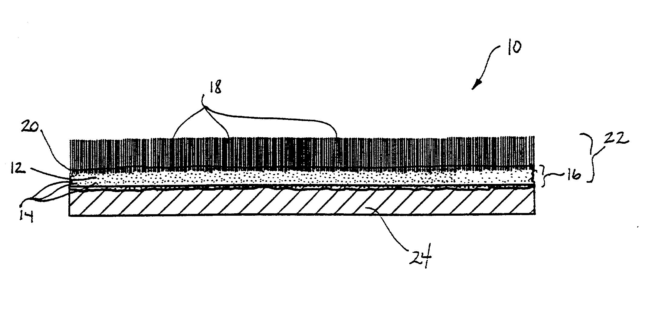
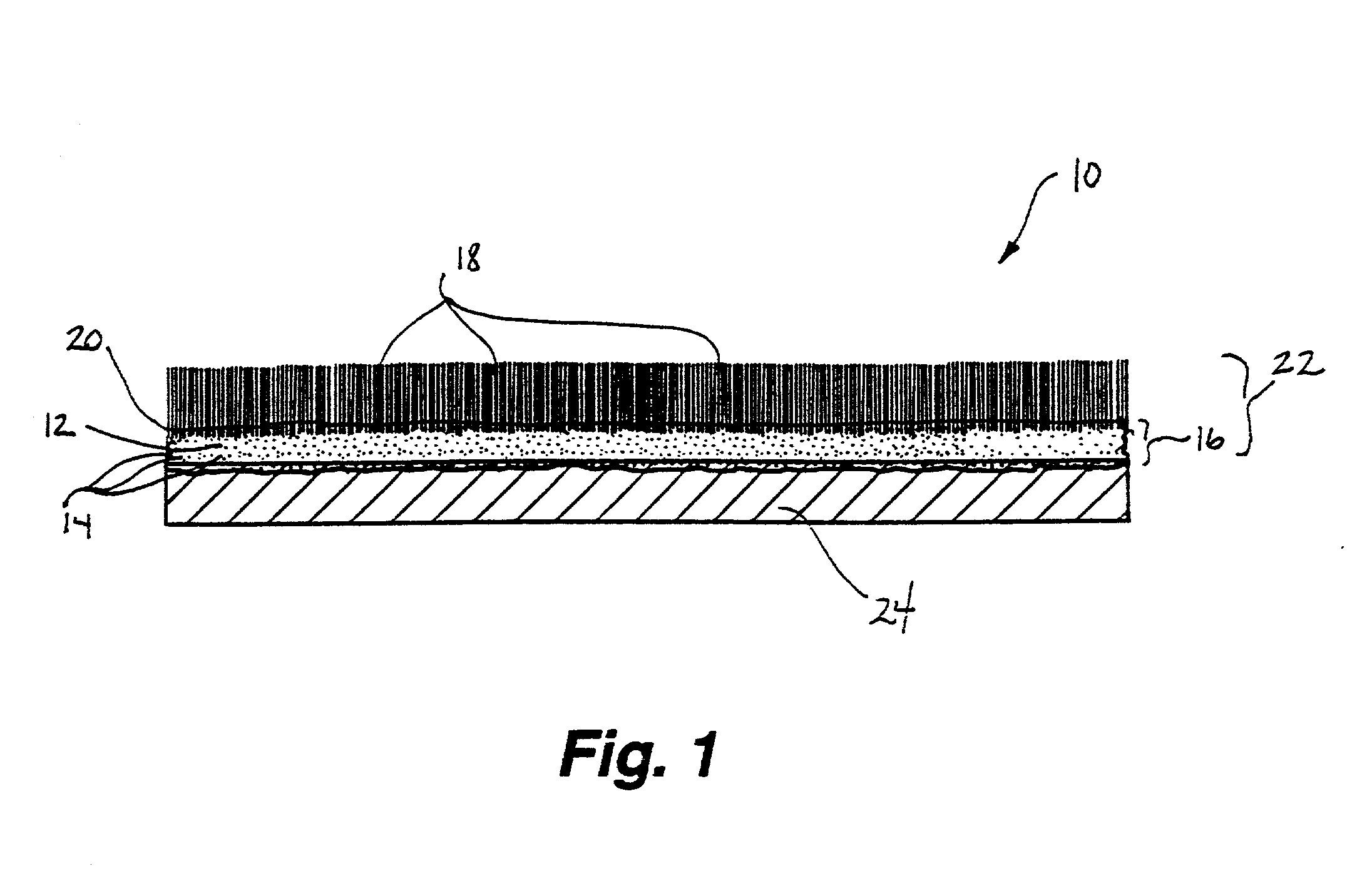
  • Fabric coating containing energy absorbing phase change material and method of manufacturing same
  • Fabric coating containing energy absorbing phase change material and method of manufacturing same

Examples


example ii

[0047] An alternative coating formulation where high phase change material content and limited extensibility is required, for example with non- or low-stretch fabrics such as non-woven or woven fabrics, is prepared as shown in Table III.

3TABLE III COMPONENT WT % DIRECTIONS Hycar XT9202 21.00 75% DOS 0.40 Strodex PK90 (90% NV) 0.33 Mix. 50% wet n-Octadecane 72.00 Add slowly to latex polymer microspheres mixture, with good mixing, dispersing microspheres well. Acrysol ASE60 (28% NV) 4.40 AF9020 (20% NV) 0.05 Hercules Advantage 831 0.30 Mix ingredients slowly until foam dissipates. Ammonium Hydroxide (28%) 1.52 Add slowly, with good mixing.

[0048] Addition of microspheres as described above in the preferred weight ratios eliminates tack and prevents blocking of the coated fabrics typically experienced with coatings having low glass transition temperature polymers such as those based on acrylic latex polymers. Tack, the tendency of material to stick to itself, can make rolls of coated fa...

example iii

[0050] A preferred foam coating formulation of the present invention may be used with breathable fabric to maintain the heat and moisture dissipation capability of the fabric. In this example, the materials are subject to mechanical frothing. Foam stabilizers are added to maintain the foam after application to the fabric. Foam stabilizers may be inorganic salts of fatty acids or their sulfate partial esters, anionic surfactants, among other compounds. Preferred foam stabilizers for use with phase change material microspheres are sodium lauryl sulfate, ammonium stearate, di-sodium-n-octadecyl sulfosuccinamate and mixtures thereof. Ammonium stearate concentrations (dry as a percent of wet coating) of 0.5% to 6% plus 0.2% to 4% sulfosuccinamate are most preferred. The coatings are prepared as shown in Table IV.

4TABLE IV COMPONENT WT % DIRECTIONS Water 4.69 75% DOS 0.20 Strodex PK90 (90% NV) 0.17 Hycar XT9202 33.74 35% wet n-Octadecane 54.53 Add slowly to above ingredients, microspheres...

example iv

[0054] Tests were conducted on acrylic fleeces in which the fibers containing microPCMs, and on non-woven materials (sometimes referred to herein as "substrate") having a coating containing microPCMs. Acrylic fleeces without microPCMs having approximately the same weight per unit area as the fleeces with microPCMs, and substrates without microPCMs having the same thickness as the non-woven substrates having a coating containing microPCMs, served as comparison materials. Specific data regarding the sample materials tested are included in Table V.

5TABLE V Acrylic Substrate Acrylic without Substrate without Materials Tested with PCM PCM with PCM PCM Wt / unit area (g / m.sup.2) 270 250 227 207 Stand thickness (mm) 5.40 5.63 0.63 0.61 Compressibility 12 16 13 20 (lbs) Raw density (kg / m.sup.3) 49 44 360 339

[0055] The content of microPCM in the acrylic fleeces was approximately 10 per cent. About 7 g / m.sup.2 microPCM was included in the coating of the non-woven substrate. This is equal to a c...


PUM

PropertyMeasurementUnit
temperatureaaaaaaaaaa
elongation at breakaaaaaaaaaa
glass transition temperatureaaaaaaaaaa

Abstract

A coating composition for fabrics includes wetted microspheres containing a phase change material dispersed throughout a polymer binder, a surfactant, a dispersant, an antifoam agent and a thickener. Preferred phase change materials include paraffinic hydrocarbons. The microspheres may be microencapsulated. To prepare the coating composition, microspheres containing phase change material are wetted ahd dispersed in a dispersion in a water solution containing a surfactant, a dispersant, an antifoam agent and a polymer mixture. The coating is then applied to a fabric. In an alternative embodiment, an extensible fabric is coated with an extensible binder containing microencapsulated phase change material to form an extensible, coated fabric. The coated fabric is optionally flocked. The coated fabrics are manufactured using transfer techniques.

Description

[0001] This application is a continuation-in-part of co-pending U.S. patent application Ser. No. 08 / 259,964 filed Jun. 14, 1994 for FABRIC COATING CONTAINING ENERGY ABSORBING PHASE EXCHANGE MATERIAL AND METHOD OF MANUFACTURING SAME, which is incorporated by reference herein, in its entirety.[0002] This invention relates to substrate coatings containing energy absorbing, temperature stabilizing phase change materials and methods of manufacturing same. More particularly, this invention relates to fabric coatings containing microspheres of phase change material dispersed in a polymer binder and methods of manufacturing same.[0003] Coatings are typically applied to fabrics to increase water resistance, water transport, insulative ability or heat storage properties of the fabrics. Recently, microencapsulated phase change materials have been described as a suitable component for fabric coatings when exceptional heat transfer and storage capabilities are desired. In particular, Internation...

Claims


Application Information

Patent Timeline
Patent Type & Authority Applications(United States)
IPC IPC(8): C09K3/00C09K5/06D04H11/00C08J3/21D06M13/02D06M15/263D06M23/00D06M23/12D06N3/00F28D20/02
CPCD04H11/00D06M23/12D06N3/0061Y10T428/2839Y02E60/145Y10T428/2982F28D20/023Y10T442/699Y10T442/2123Y10T442/259Y10T442/2131Y10T442/3008Y10T442/2213Y10T442/601Y02E60/14
Inventor ZUCKERMAN, JOSEPH L.PUSHAW, ROBERT J.PERRY, BERNARD T.WYNER, DANIEL M.
Owner OUTLAST TECH LLC
Learn More