Differential amplifier with gain substantially independent of temperature

a technology of gain and amplifier, applied in amplifiers, amplifiers with semiconductor devices/discharge tubes, electrical devices, etc., can solve problems such as low output voltage of common mode, large chip area for integration onto a single chip, and limited gain by resistor ratio

Inactive Publication Date: 2003-02-27
UNIVERSITE CATHOLIQUE DE LOUVAIN
View PDF6 Cites 8 Cited by
  • Summary
  • Abstract
  • Description
  • Claims
  • Application Information

AI Technical Summary

Problems solved by technology

There are several problems with this known device.
First of all the gain is limited by the resistor ratio obtainable.
Secondly, integration onto a single chip requires a lot of chip area for the resistors and ...

Method used


Image

  • Differential amplifier with gain substantially independent of temperature
  • Differential amplifier with gain substantially independent of temperature
  • Differential amplifier with gain substantially independent of temperature

Examples


first embodiment

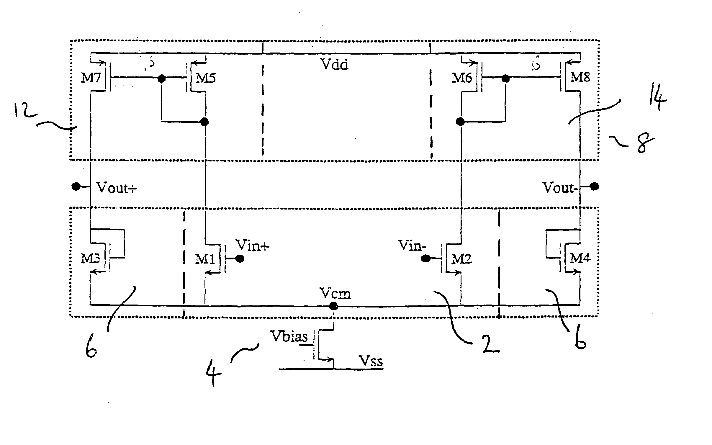
[0031] the present invention is shown schematically in FIG. 2. It is a fully differential amplifier and comprises an input branch 2 comprising a differential and common mode input of, for instance, a matched pair of transistors M1 and M2 of a first conductivity type, e.g. NMOS, with one of their main current electrodes connected together, e.g. their sources. The output branch 6 comprises a second differential and common mode device comprising two matched transistors M3 and M4 having the first conductivity type, e.g. NMOS, and being diode connected, for example, the gate and drain electrodes connected together. The one main current electrodes of transistors M3 and M4 are connected to the one main current electrodes of the input pair M1 and M2 so that these all lie on the same potential. This one common electrode, e.g. source, is connected to a voltage or current source 4 depending on the application and the required performance. The one common electrode for M1 to M4 avoids the need o...

third embodiment

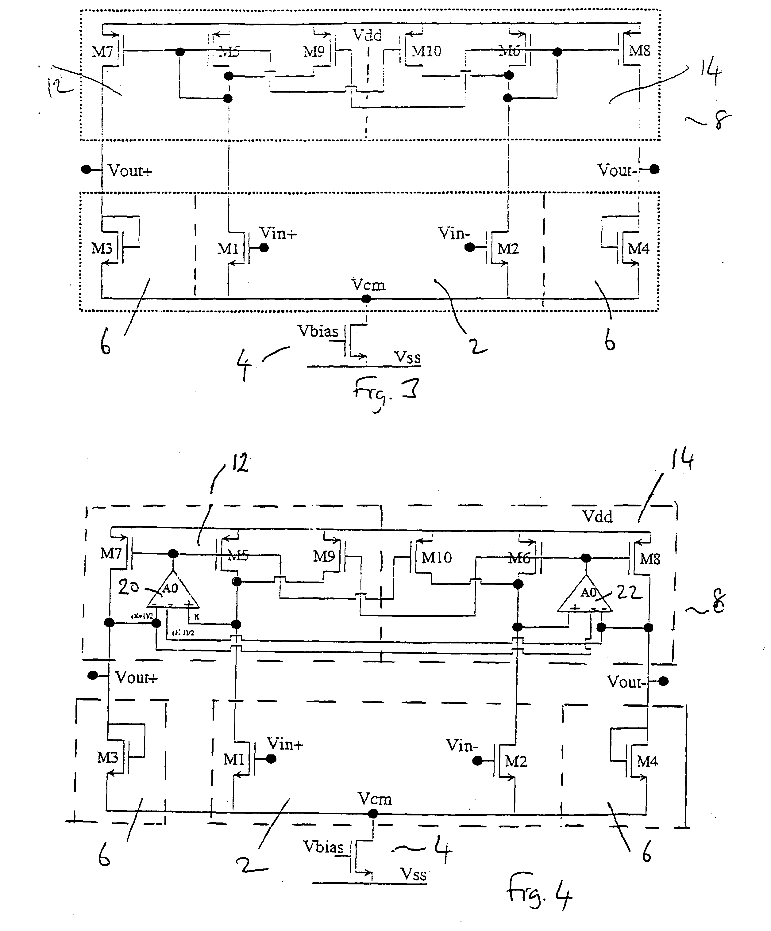
[0042] Although the amplifier of FIG. 3 is a considerable improvement, the effect of the output conductance (gd) of the transistors has been ignored. The Early voltage effect leads to a parasitic impedance in parallel with the circuit transductance. Early voltage can lead to a temperature dependence of gain. In accordance with the present invention an asymmetrical single ended operational transductance (OTA) amplifier 20, 22 is used to regulate the half current mirrors 12, 14 as shown in FIG. 4. This provides a very weak temperature dependence of the gain as well as a precise gain. To achieve this the amplifiers 20, 22 must have a different gain for their positive and negative inputs, hence the name "asymmetrical". An equivalent circuit of an asymmetrical amplifier 20 in accordance with an embodiment of the present invention is shown in FIG. 5. The asymmetrical amplifier has an input device which comprises two signal inputs. This input device will be called an "equivalent input" of ...


PUM


Abstract

A differential amplifier is described comprising an input branch for receiving differential and common mode input signal components; an output branch providing differential and common mode output signal components; and the differential amplifier being adapted to set a relationship between the magnitude of the common mode output signal component level of the amplifier with respect to the magnitude of the common mode input signal component level to the input stage so that the common mode output signal component level intrinsically follows the common mode input signal component level as a common mode follower without using feedback control of the common mode output signal component. Also an asymmetrical amplifier is described which may be advantageously used as a component of the differential amplifier.

Description

[0001] The present invention relates to a differential amplifier, particularly to an instrumentation preamplifier or sensor differential amplifier. Such amplifiers preferably have constant gain over a wide temperature range. The present invention also relates to an asymmetrical differential amplifier with differing gains on its two inputs.TECHNICAL BACKGROUND[0002] In analog circuitry, signals are often represented by differential signals, e.g. voltages or currents. A differential signal may be described by a common mode component and a differential component. The common mode component may be looked upon as the average of two signals whereas the differential component is the difference between the same signals. Preferably, a differential amplifier has a high immunity to common mode changes or noise (high common mode rejection) and is therefore often preferred compared to a single end amplifier. Different applications place different requirements on a differential amplifier, for inst...

Claims


Application Information

Patent Timeline
IPC IPC(8): H03F3/45
CPCH03F3/45183H03F3/4565H03F3/45659H03F2203/45644H03F2203/45658H03F2203/45682
Inventor DESSARD, VINCENTFLANDRE, DENISE
Owner UNIVERSITE CATHOLIQUE DE LOUVAIN
Why Eureka
Try Eureka