Methods for embossing and embossed articles formed therby

a polymer surface and embossing technology, applied in the field of embossing of polymeric surfaces, can solve the problems of unsatisfactory head-disk interaction, inability to achieve nanometer-scale precision, and difficulty in embossing polymer surfaces having high glass transition temperatures, so as to improve the adhesion of the embossed polymer surface and improve the release of polymeric surfaces

Inactive Publication Date: 2003-03-27
SABIC INNOVATIVE PLASTICS IP BV
View PDF30 Cites 31 Cited by
  • Summary
  • Abstract
  • Description
  • Claims
  • Application Information

AI Technical Summary

Benefits of technology

0080] In another embodiment, the incorporation of fluorine atoms, silicon atoms, or siloxane segments into the backbone of polymer improves the release of a polymeric surface from an embossing tool. For polyimides, this may be achieved by use of one or more of the diamine or dianhydride structures of formula VIIIa, VIIIc, IXa, or IXb. The degree of release may be adjusted by variation in the identity and quantity of the fluorine and/or silicone atom containing monomers. Additionally, the polymer containing the fluorine atom, silicone atom or siloxane segments may be blended with perfluorocarbon polymers described above in order to adjust the degree of release. If adhesion is desired in lieu of release,...

Problems solved by technology

Deeper features or features that vary outside the ranges can be produced, but, in general, for flying head applications, these can result in undesirable head-disk interactions.
It is presently difficult to emboss polymer surfaces having high glass transition temperatures with nanometer-scale precision because extremely elevated temperatures (well above the glass transition) are required to ensure adequate flow and pattern replication.
Under these conditions, there is potential to not only degrade the polymer surface, but also damage the substrate or surrounding sensitive layers and features.
When using either high or low glass transition polymers, another drawback associated with embossing methods such as hot stamping is the significant degree of adhesion that ca...

Method used


Image

  • Methods for embossing and embossed articles formed therby
  • Methods for embossing and embossed articles formed therby
  • Methods for embossing and embossed articles formed therby

Examples


example 10

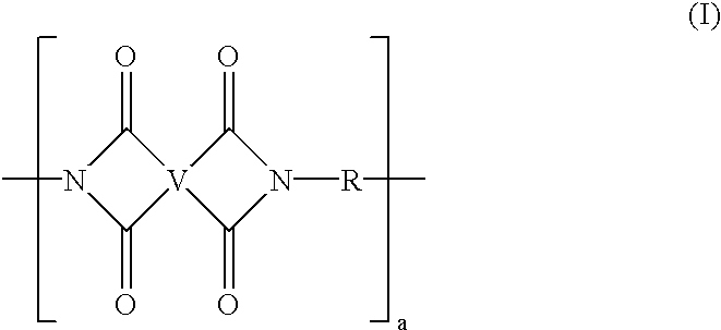
[0098] Pyralin 2611 a commercially available polyimide (from HD Microsystems) in polyamic acid form in NMP solvent was coated onto a glass substrate. The coated disk was then soft-baked at 150.degree. C. for 2 hours whereupon the disk was placed in an embossing press and embossed at 150.degree. C. with an optical disk stamper having a digital versatile disk (DVD) format. Following embossing, the disk was placed in an oven which was ramped from 150 to 300.degree. C. over 1 hour and held at 300.degree. C. for 1 hour to cure the polymer. Once baked the polymer possessed a glass transition temperature Tg2 of greater than 300.degree. C. and the pre-embossed pattern was maintained. In contrast, embossing of a pre-cured Pyralin 2611 polymer at 150 .degree. C. resulted in no pattern transfer.

[0099] The method of embossing described in the above embodiments provides several advantages that allow the production of improved embossed surfaces. Defects caused by thermal and chemical decompositio...


PUM

PropertyMeasurementUnit
Temperatureaaaaaaaaaa

Abstract

A method for manufacturing an embossed surface comprising a polymer with a first glass transition temperature Tg1 comprises embossing the surface a temperature Temb; and raising the first glass transition temperature Tg1 of the embossed polymeric surface to a second glass transition temperature Tg2 such that Tg2>Temb. In another embodiment, a method for improving the release of a polymeric surface from an embossing tool comprises incorporating of one or more of fluorine atoms, silicon atoms, or siloxane segments into the backbone of polymer. The methods are particular suited for direct patterning of photoresists, fabrication of interdigitated electrodes, and fabrication of data storage media.

Description

[0001] This application claims priority to U.S. Serial No. 60 / 285,323, filed Apr. 19, 2001, the entire contents of which are incorporated herein by reference.BACKGROUND OF INVENTION[0002] This disclosure relates to the embossing of polymeric surfaces, and the articles formed thereby.[0003] Optical, magnetic, and magneto-optic media are primary sources of high performance storage technology, allowing both high storage capacity and reasonable cost per megabyte of storage. One such type of media generally comprises a substrate covered by a polymer film. The film can be embossed to provide, for example, pits, grooves, asperities, bit patterns, servo-patterns, and edge features. The desired surface quality can also be embossed e.g., to obtain a desired smoothness, roughness, flatness, microwaviness, and texture, e.g., microtexturing for magnetic grain orientation. The embossed surface features can have a depth of up to about 200 nanometers (nm). Deeper features or features that vary outs...

Claims


Application Information

Patent Timeline
IPC IPC(8): B29C59/00B29K27/06B29K79/00C08G73/10B29C59/02G11B5/74G11B5/84G11B7/24G11B7/241G11B7/26G11B11/105H01B3/30
CPCB29C59/005C08G73/10C08G73/1039C08G73/1042C08G73/106C08G73/1064C08G73/1067C08G73/1071G11B5/74G11B5/8404G11B7/241G11B7/263G11B11/10582H01B3/306B29C59/02
Inventor REITZ, JOHN BRADFORDGORCZYCA, THOMAS BERTCELLA, JAMES ANTHONY
Owner SABIC INNOVATIVE PLASTICS IP BV
Why Eureka
Try Eureka