System and method for effecting high-power beam control with outgoing wavefront correction utilizing holographic sampling at primary mirror, phase conjugation, and adaptive optics in low power beam path

a technology of adaptive optics and beam path, applied in the field of optics, can solve the problems of reducing durability and/or increasing manufacturing cost, limiting the performance of conventional adaptive optics systems using deformable mirrors, and delicate optical devices in the path of high-power energy beams

Inactive Publication Date: 2003-04-03
RAYTHEON CO
View PDF17 Cites 25 Cited by
  • Summary
  • Abstract
  • Description
  • Claims
  • Application Information

AI Technical Summary

Problems solved by technology

Unfortunately, the use of delicate optical devices in the path of a high-power energy beam is problematic.
Therefore, coatings may need to be applied at lower than optimal temperature using more complex coating processes, thereby reducing durability and/or increasing manufacturing cost.
In addition, conventional adaptive optics systems using deformable mirrors are limited in performance.
There is also a limitation with respect to the number actuators that can be used.
The stroke of the conventional deformable mirror is limited.
Further, a conventional continuous face sheet deformable mirror cannot correct for a pathology in the spatial phase pattern, such as a branch point or an abrupt phase discontinuity.
However, this scheme is practical only with a coherently-combined array of single-mode fiber amplifiers, as each fiber channel is correctable in piston only, not high order.
Also, this scheme is not applicable to multi-mode laser media such as large core fiber amplifiers or

Method used


Image

  • System and method for effecting high-power beam control with outgoing wavefront correction utilizing holographic sampling at primary mirror, phase conjugation, and adaptive optics in low power beam path
  • System and method for effecting high-power beam control with outgoing wavefront correction utilizing holographic sampling at primary mirror, phase conjugation, and adaptive optics in low power beam path
  • System and method for effecting high-power beam control with outgoing wavefront correction utilizing holographic sampling at primary mirror, phase conjugation, and adaptive optics in low power beam path

Examples


embodiment 100

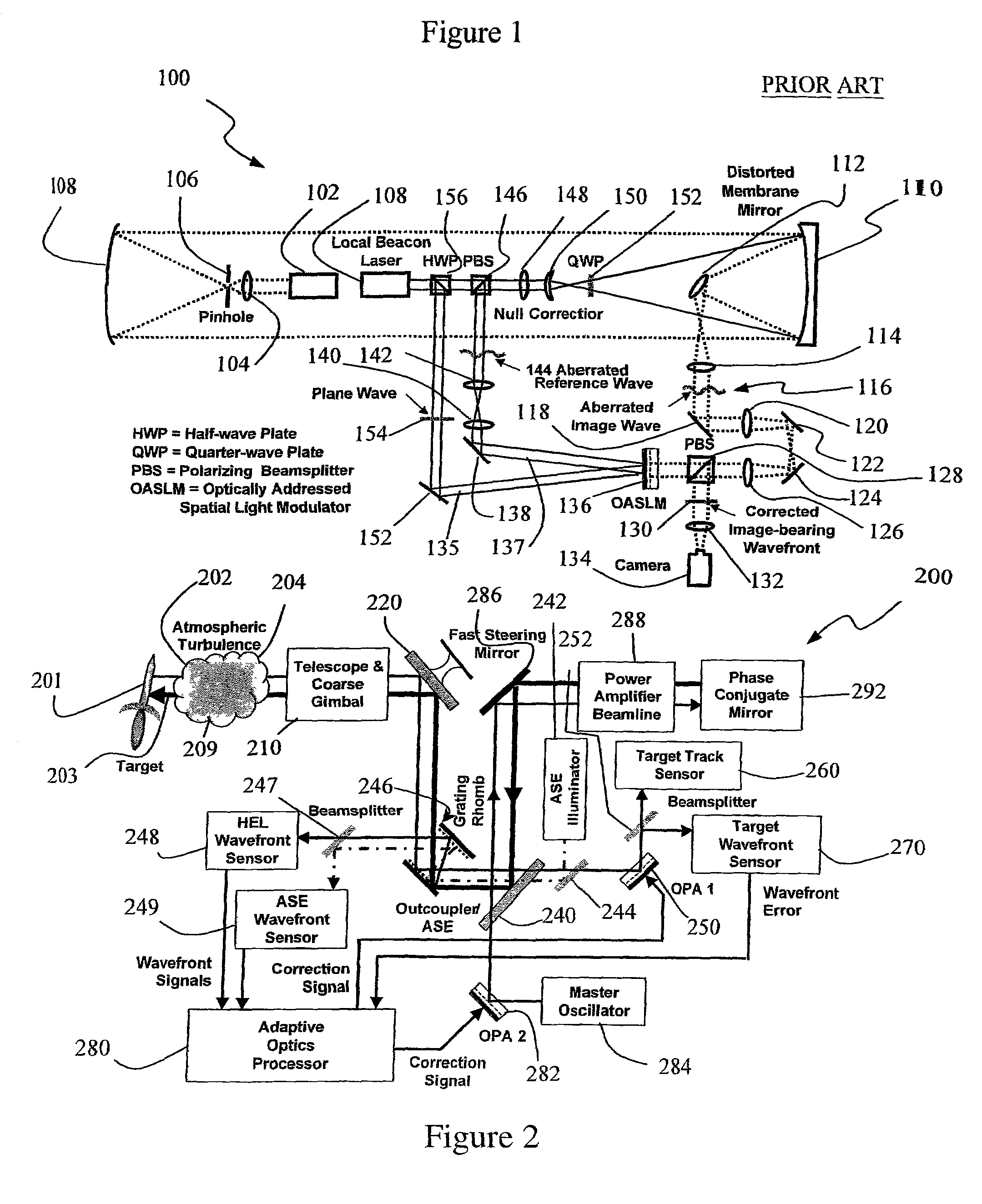
[0029] The system shown in FIG. 1 is representative of the work done by Gruneisen, Peters, and Wilkes and others in this field. In this embodiment 100, an optical aberration is recorded on an Optically Addressed Spatial Light Modulator (OASLM) 136 with a pair of laser beams. One beam 135 has a plane wave phase profile and serves as the "reference" beam. The other 137 has a phasefront on which is encoded the aberration 144 of the distorting element to be corrected. These beams are caused to interfere at the OASLM 136 and the resulting dark and light interference fringes are detected by a photo-sensitive layer (photo-conductor or photodiode) within the OASLM 136, which converts the optical fringes into an electric field profile. In holography, this is known as the "read" process. The spatially varying electric field then "writes" the interference pattern onto a nematic or ferroelectric liquid crystal layer, which responds to the varying field profile by reorienting the direction of th...

embodiment 500

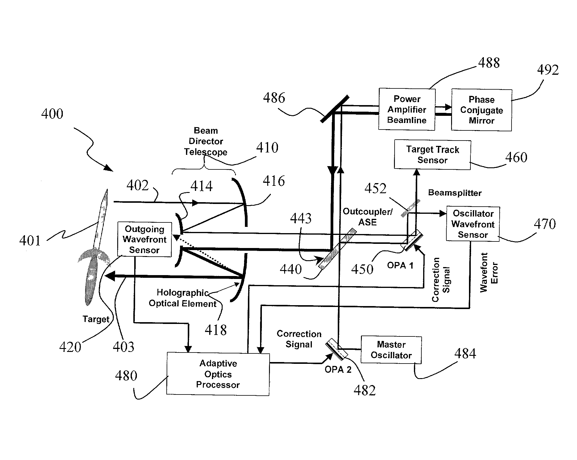
[0045] FIG. 5 shows a preferred embodiment of the invention. In FIG. 5, non-common path error correction is accomplished with a second phase conjugate leg, thereby eliminating the Oscillator Wavefront Sensor, OPA 2, and a portion of the functionality of the Adaptive Optics Processor, utilized in FIGS. 3 and 4. In this embodiment, the Master Oscillator 552 is moved to the Oscillator Wavefront Sensor 470 location in FIG. 4; and both OPA 2 (482) and the Master Oscillator 484 thereof are replaced by a second Phase Conjugate Mirror 546. A Preamplifier 544 may be used in the second phase conjugate leg to overcome reflective losses in the Outcoupler / ASE 540 on the vertical beam path from the second phase conjugate leg up to the first leg containing a Power Amplifier Beamline 554. This HEL architecture may have cost and complexity advantages for certain system configurations.

[0046] In this embodiment, outgoing wavefront sampling and sensing are identical to those described with reference to...


PUM


Abstract

A beam control system and method. In an illustrative embodiment, the inventive system (500) provides a first beam of electromagnetic energy (503); samples the first beam (503) and provides a second beam (505) in response thereto; detects aberrations in the second beam (505); and corrects aberrations in the first beam (503) in response to the detected aberrations. In a specific implementation, the invention (500) includes a beam director telescope (510) having a primary mirror (516) on which a holographic optical element (518) is disposed. The holographic optical element (518) samples the output high-power beam and provides a sampled beam to a wavefront sensor (520). The wavefront sensor (520) provides signals to an adaptive optics processor (580). The adaptive optics processor (580) analyzes the sampled wavefront, detects aberrations therein and provides a correction signal to an optical phased array (550). A master oscillator (552) provides a reference beam, which reads the optical phased array (550) and is back reflected off a front surface of an aperture sharing element (540). The resulting beamfront is conjugated by a first phase conjugate mirror (546) and then again by a second phase conjugate mirror (556). The output of the second phase conjugate mirror (556) is amplified and reflected off the front surface of the aperture sharing element (540). The aperture sharing element (540) outputs the high power beam via the telescope (510) which is corrected for the optical distortions in the telescope and beam path.

Description

[0001] 1. Field of the Invention[0002] The present invention relates to optics. More specifically, the present invention relates to systems and methods for directing and correcting high-power beams of electromagnetic energy.[0003] 2. Description of the Related Art[0004] Directed energy weapons and specifically high-energy laser (HEL) weapons are being considered for variety of military applications with respect to a variety of platforms, e.g., spaceborne, airborne and land based systems to name a few. These weapons generally involve the use of the laser or other source of a high-energy beam to track and destroy a target. To achieve mission objectives, directed energy weapons must be accurately steered and optimally focused. Steering involves line-of-sight control while focusing, with respect to HEL weapons, involves wavefront error correction. Currently, wavefront error correction is typically achieved using adaptive optics. The current state of the art in laser beam control adaptiv...

Claims


Application Information

Patent Timeline
IPC IPC(8): G02B26/06G02B27/00
CPCG02B27/0037G02B26/06
Inventor BYREN, ROBERT W.TRAFTON, ALVIN F.
Owner RAYTHEON CO
Why Eureka
Try Eureka