Apparatus for rapid measurement of aerosol bulk chemical composition

a technology of aerosol and bulk chemical composition, which is applied in the direction of chemical methods analysis, instruments, separation processes, etc., can solve the problems of inability to immediately understand and interpret the results, inability to adjust the sampling strategy and protocol in the field, and long sampling intervals, so as to minimize the contribution of vapor condensate and improve the effect of droplet collection

Inactive Publication Date: 2003-05-01
BROOKHAVEN SCI ASSOCS +1
View PDF3 Cites 51 Cited by
  • Summary
  • Abstract
  • Description
  • Claims
  • Application Information

AI Technical Summary

Benefits of technology

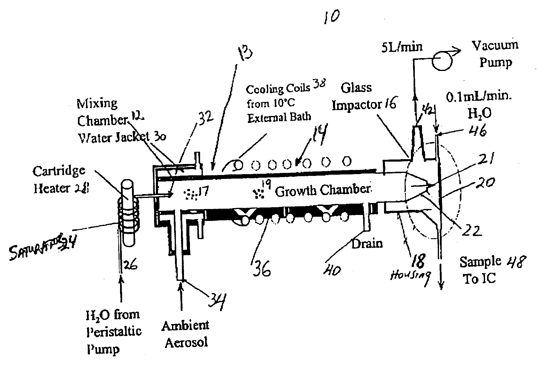
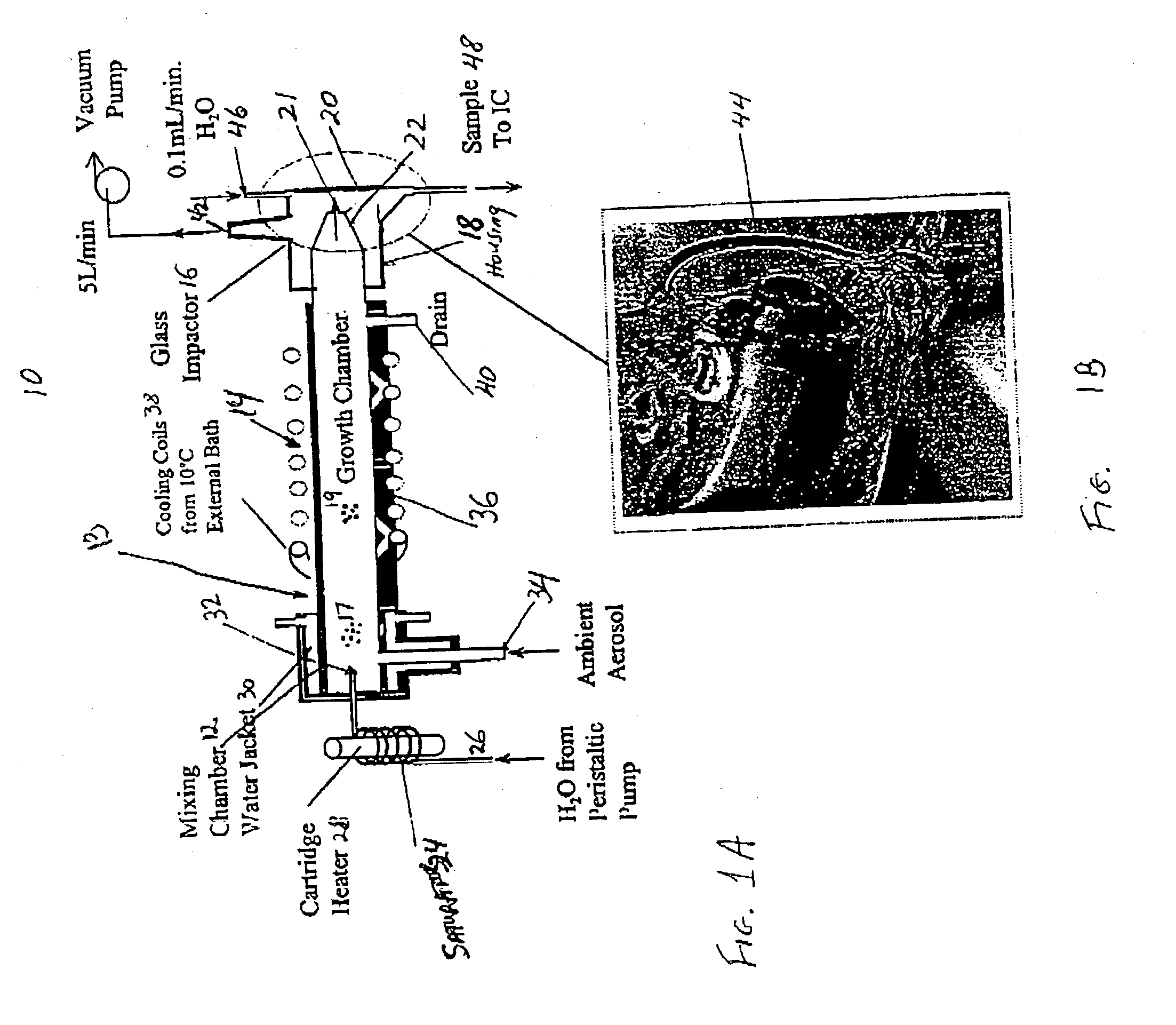
0090] As with other enhancements present in PILS II, changes made to the inertial impactor resulted in a significant improvement in droplet collection by comparison to PILS I. In PILS I the impactor was a flat glass plate. In PILS I a significant amount of water vapor that existed in the growth region condensed on the impactor plate along with the captured droplets that contain the species to be measured, and the combined flow was collected at the bottom of the impactor. Extensive cooling in the growth region was necessary to minimize the contribution of vapor condensate on the impaction plate and thus minimize dilution of the liquid containing the aerosol constituents to be detected. By contrast, the impactor of PILS II can separate more effectively the wall condensate and the collected droplets, concentrating the liquid supplied to the IC, and improving the LOD of the method when IC sample loops are employed.
0091] When operating, air containing the grown aerosol particles impinged onto the quartz surface 70 where the aerosol particles impact. Liquid from these captured aerosol particles was pushed to the perimeter of the quartz plate 70 by the radial spreading air jet and merged with the transport flow introduced through the top of the conical-shaped housing cavity 73. The combined flow was drawn out from the bottom of the conical cavity 73. Outside the cavity, yet within apparatus 60, the surface of the impactor body is angled away from the cavity so that water vapor condensed on the tilted surface flows away and out of the impactor through a drain line. In this way, the wetted area where the sample was collected was minimized and most of the excess condensed water was separated from the liquid containing the dissolved aerosol species. The volume of liquid collected from the collection device 66, and hence sample-dilution, can be adjusted through selection of the transport flow.
0092] As a result of enhancements made in the design of the inertial impactor, PILS II can collect droplets at rates much higher than 5 lpm, the limit that could be reached with PILS I. For example, the enhanced collector of PILS II, can now collect droplets at rates higher than 7 lpm and preferably in a range from about 10 lpm to about 20 lpm. A higher sample flow rate increases the mass of collected aerosol particles resulting in improved LOD and a faster instrument response. This characteristic is especially important when measuring low concentrations of aerosol particles such as are found in an aircraft or in remote areas.

Problems solved by technology

Unfortunately, although widely used, this approach has many drawbacks.
Additionally, depending on flow rates and ambient concentrations, the sampling intervals are long, typically hours to days.
Faster measurements are possible but often impractical due to the labor involved in filter preparation and sample extraction.
Since the turn-around time for processed results also tends to be long, immediate insight and interpretation of these results are generally not available for in-the-field adjustment and modifications of experiment sampling strategies and protocols.
In addition, off-line techniques are also prone to potential sampling artifacts, particularly for volatile aerosol components.
Pressure drops within the sampler can also contribute to volatility losses.
These artifacts have led to complicated filter pack sampling systems using multiple filters of various types to capture volatile aerosol components.
Combined, these processes can lead to significant uncertainties, particularly when measuring mass concentrations of volatile or easily contaminated aerosol chemical components, such as nitrate, ammonium, and semi-volatile organic species.
Unfortunately, they tend to be complex and costly, and the measurements generally do not give quantitative information on particle composition.
Although they do not provide size-resolved information as do mass spectrometer-based instruments, these approaches are quantitative.
Drawbacks associated with these techniques include aerosol losses, greater complexity due to the need for sample pre-concentration, and slow time response due to the time needed to drain large wetted areas.

Method used


Image

  • Apparatus for rapid measurement of aerosol bulk chemical composition
  • Apparatus for rapid measurement of aerosol bulk chemical composition
  • Apparatus for rapid measurement of aerosol bulk chemical composition

Examples


example 1

Results from the Atlanta EPA Supersite Study for PILS I

[0110] PILS I was tested during 1999 at the Atlanta EPA Supersite experiment where a large assembly of aerosol equipment was being tested for their performance. As the first EPA Supersite, our experiments were aimed at intercomparing various techniques for measuring chemical composition of particles smaller than 2.5 micrometer diameter, so-called PM2.5. A secondary goal was to study the chemical and physical properties of urban PM2.5 aerosol particles in the southeastern United States. Preliminary results showed that the PILS agreed well with other semi-continuous techniques, and were in general agreement with filter measurements of non-volatile species, such as sulfate.

[0111] The particles bearing diameter less than 2.5 micrometer (PM2.5) for sampling system, including the PILSI-IC, are shown in FIG. 7. The sampling inlet consisted of an inverted stainless steel tube connected to a 10 L min.sup.-3, 2.5 micrometer cut URG (Unive...

example 2

Calibration Results of Particle Collection Efficiency for PILS II

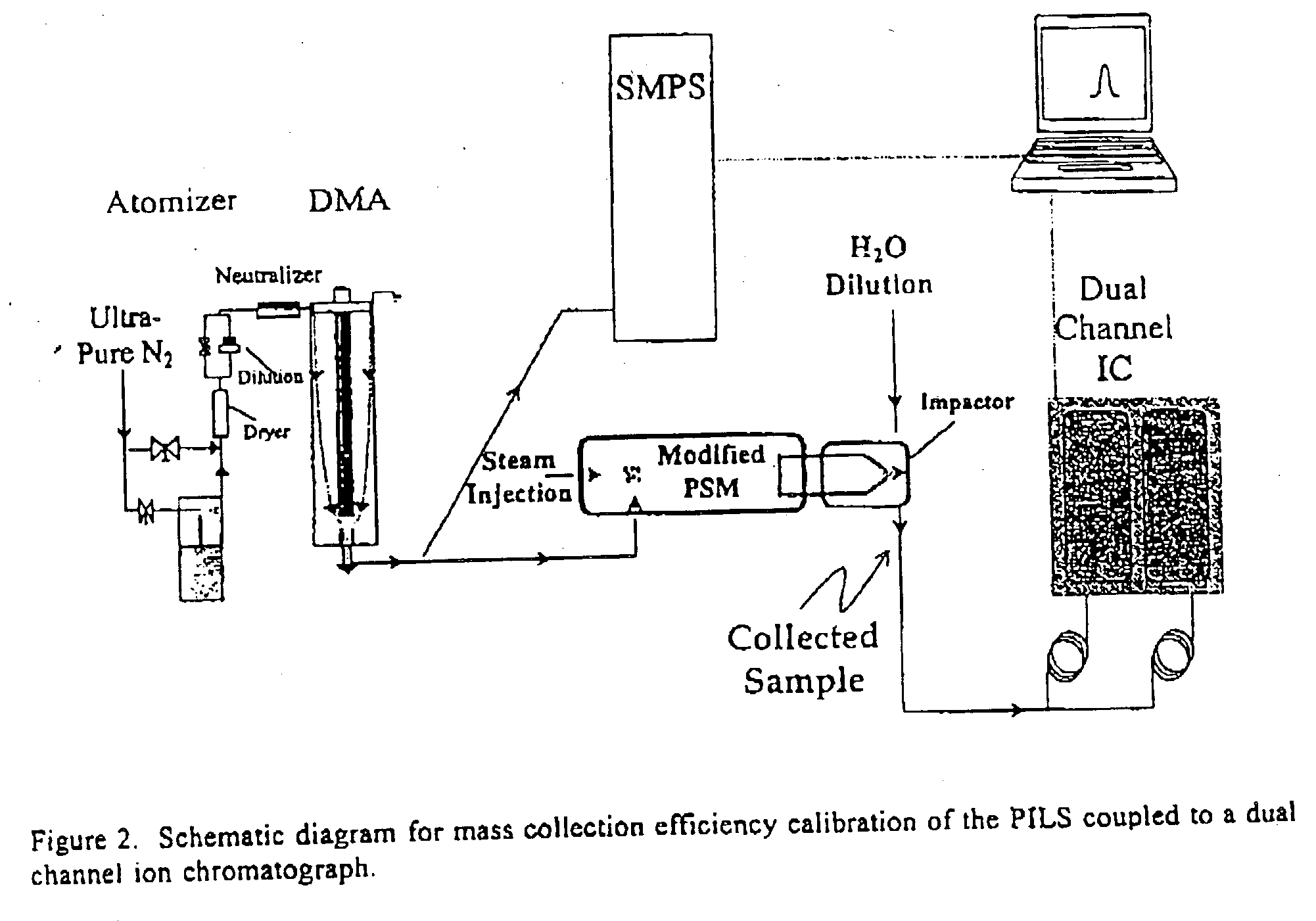
[0116] In order to calibrate the size-dependant collection efficiency of PILS II, two standard methods of particle generation were needed to cover the large particle size range as shown in FIG. 12. For particle diameters Dp>1 .mu.m, a vibrating orifice aerosol generator (VOAG) (VOAG 3450, TSI Inc, St Paul Minn.) produced aerosols out of a solution of olive oil (0.1-10%) and propanol, tagged with a small amount of flouresceine (0.01%, Aldrich Chemical). The size of the aerosols generated depended on the fraction of olive oil in solution and the VOAG operating frequency. The VOAG illustrated in FIG. 12 was turned upside-down to maximize transport of large particles in about 2 l min.sup.-1 of nitrogen dilution air. An aerodynamic particle sizer (APS) located just before the PILS, monitored the diameter of the generated aerosol. To accommodate the total flow of PILS II and APS, 18 l min.sup.-1 of dried ambient room air was...


PUM

PropertyMeasurementUnit
diameteraaaaaaaaaa
lengthaaaaaaaaaa
diameteraaaaaaaaaa

Abstract

An apparatus for continuous on-line measurement of chemical composition of aerosol particles with a fast time resolution is provided. The apparatus includes an enhanced particle size magnifier for producing activated aerosol particles and an enhanced collection device which collects the activated aerosol particles into a liquid stream for quantitative analysis by analytical means. Methods for on-line measurement of chemical composition of aerosol particles are also provided, the method including exposing aerosol carrying sample air to hot saturated steam thereby forming activated aerosol particles; collecting the activated aerosol particles by a collection device for delivery as a jet stream onto an impaction surface; and flushing off the activated aerosol particles from the impaction surface into a liquid stream for delivery of the collected liquid stream to an analytical instrument for quantitative measurement.

Description

[0001] This application is a continuation-in-part of U.S. application Ser. No. 09 / 679,704 filed on Oct. 5, 2000, entitled "An Apparatus for Rapid Measurement of Aerosol Bulk Chemical Composition," which is incorporated herein by reference.[0003] 1. Field of Invention[0004] The invention relates to an apparatus for rapid automated on-line continuous measurement of chemical composition of ambient aerosol particles. This invention also relates to a method of analyzing the chemical composition of ambient aerosol particles.[0005] 2. Description of Related Art[0006] There have been many devices built and many processes developed to understand the sources, atmospheric transformation, fate and health effects of ambient aerosols. All require knowledge of particle chemical composition. Most processes using these devices are quantitative composition measurements, typically performed off-line on particles collected onto substrates by filtration or inertial impaction. Samples collected on the su...

Claims


Application Information

Patent Timeline
Patent Type & Authority Applications(United States)
IPC IPC(8): G01N15/02G01N15/06G01N30/02
CPCG01N15/0255G01N15/065G01N30/02G01N2015/0261Y10T436/235Y10T436/25625Y10T436/25Y10T436/25875G01N2015/0681B01D15/36
Inventor LEE, YIN-NAN E.WEBER, RODNEY J.ORSINI, DOUGLAS A.
Owner BROOKHAVEN SCI ASSOCS
Why Eureka
Try Eureka