In general, when using a conventional
induction logging tool with transmitters and receivers (induction coils) oriented only along the borehole axis, the
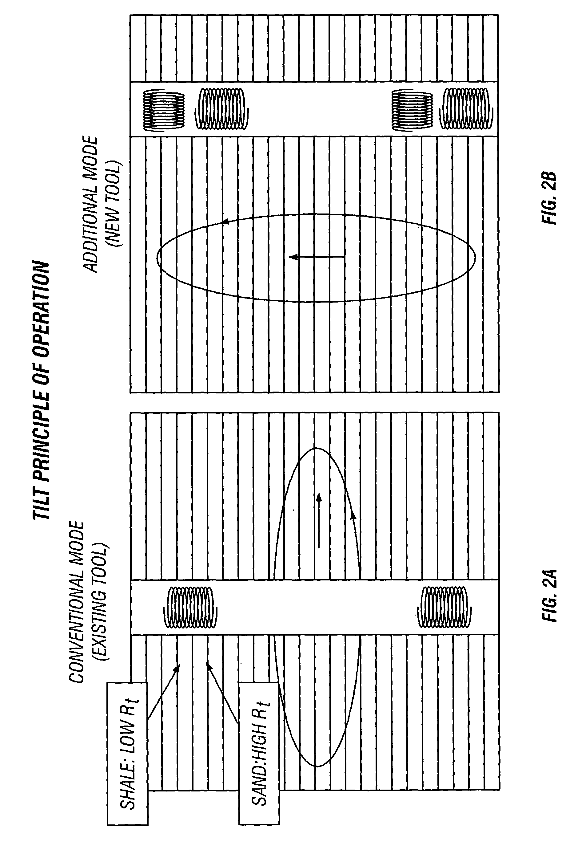
hydrocarbon-bearing zones are difficult to detect when they occur in multi-layered or laminated reservoirs.
These reservoirs usually consist of thin alternating
layers of shale and sand and, oftentimes, the
layers are so thin that due to the insufficient resolution of the conventional
logging tool they cannot be detected individually.
Conventional induction logging devices, which tend to be sensitive only to the horizontal
conductivity of the formations, do not provide a measure of vertical
conductivity or of
anisotropy.
One, if not the main, difficulties in interpreting the data acquired by a transversal induction logging tool is associated with
vulnerability of its response to borehole conditions.
However, even with these modifications, the data logs obtained with a conventional transversal induction logging instrument can be difficult to interpret, that has been exacerbated while logging through a sequence of
layers.
There are a few hardware margins and
software limitations that
impact a conventional transversal induction logging tool performance and result in errors appearing in the acquired data.
The general hardware problem is typically associated with an unavoidable electrical field that is irradiated by the tool induction transmitter simultaneously with the desirable
magnetic field, and it happens in agreement with Maxwell's equations for the time varying field.
The transmitter electrical field interacts with remaining modules of the induction logging tool and with the formation; however, this interaction does not produce any useful information.
Indeed, due to the always-existing possibility for this field to be coupled directly into the receiver part of the sensor section through parasitic displacement currents, it introduces the
noise.
When this
coupling occurs, the electrical field develops undesirable electrical potentials at the input of the receiver
signal conditioning, primarily across the
induction coil receiver, and this
voltage becomes an additive
noise component to the
signal of interest introducing a
systematic error to the measurements.
The problem could become even more severe if the induction logging tool operates in wells containing water-based fluids.
This circumstance apparently would result in a fact that
capacitive coupling and associated systematic errors are environment dependant because capacitive impedance will be converse to the well mud
permittivity.
However, geometry and
layout effectiveness of Faraday shields becomes marginal and contradictory in the
high frequency applications where conventional transverse induction tools can operate.
These limitations occur due to the attenuation these shields introduce to the
magnetic field known in the art as a shield "
skin effect".
The shield design limitations are unavoidable and, therefore, the possibility for the coupling through displacement currents remains.
Another source of hardware errors introduced into the acquired
log data is associated electrical
potential difference between different tool conductive parts and, in particular, between transmitter and receiver pressure housings if these modules are spaced apart or galvanically separated.
It can be noticed that employing the induction tool in the logging string where it has mechanical and electrical connections (including
telemetry) with instruments positioned both above and below could also result in the appearance of the above-mentioned currents.
The time varying currents also generate a respective magnetic field that crosses induction receiver coils and induces error voltages.
Unfortunately, these error voltages are also environmentally dependent and their changes cannot be sufficiently calibrated out during tool manufacturing.
Another source of systematic errors introduced in the
log data is directly determined by uncertainties in mechanical dimensions of multi-component transmitter and receiver coils in the sensor section related both to their overall dimensions and positions with respect to each other.
However, even slight physical
assembly deviations in the coil wires position and non-uniform coil form material temperature dependencies might destroy a factory pre-set bucking (compensation of the transmitter primary magnetic field coupled in the
receiver coil) during well logging, and create non-recoverable errors due to mechanical displacement or imperfections.
Another limitation found in certain induction
instrumentation systems is that an insufficient number of signal samples that are gathered for appropriate data stacking.
Such data insufficiency occurs due to the necessary measurement "
idle time" required for sequentially changing the operational transmitter frequency in a switched frequency tool.
If during this "
idle time" the tool continues to take samples or measurements, these measurements will be inaccurate and essentially useless.
Therefore, prior receiver designs have provided for "
idle time" windows in the measurements during transient
decay time, thereby potentially stacking a relatively small and possibly insufficient number of data samples.
Each of the above-mentioned problems, by itself or a combination with another problem adds to the
data error, thereby decreasing the accuracy of the induction downhole tool samples and measurements.
Finally, as discussed in the U.S. Pat. No. 3,124,742 by Schneider, galvanic electrodes used in conjunction with induction coils are useful, however, subject to the above mentioned problems.


