

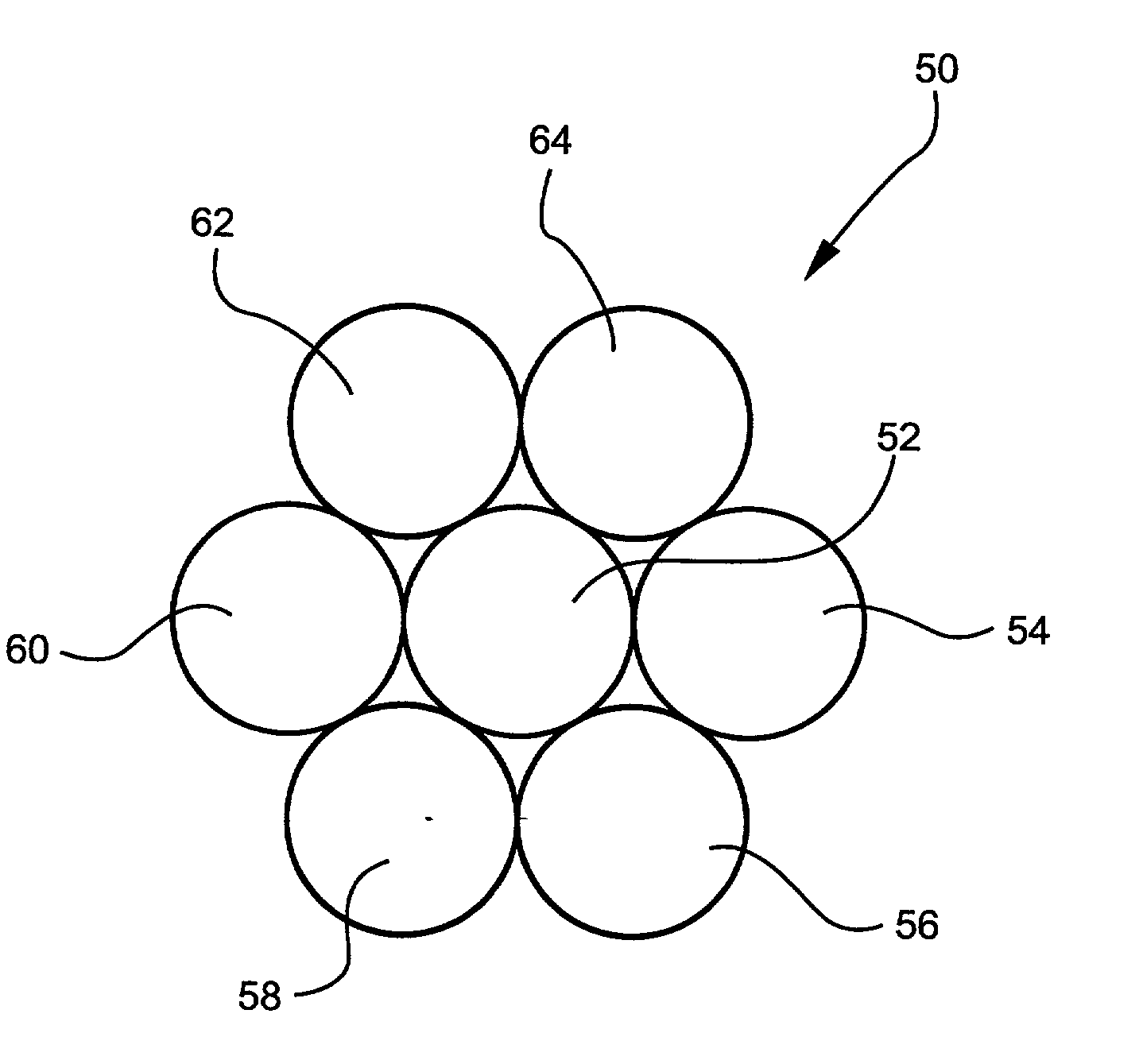
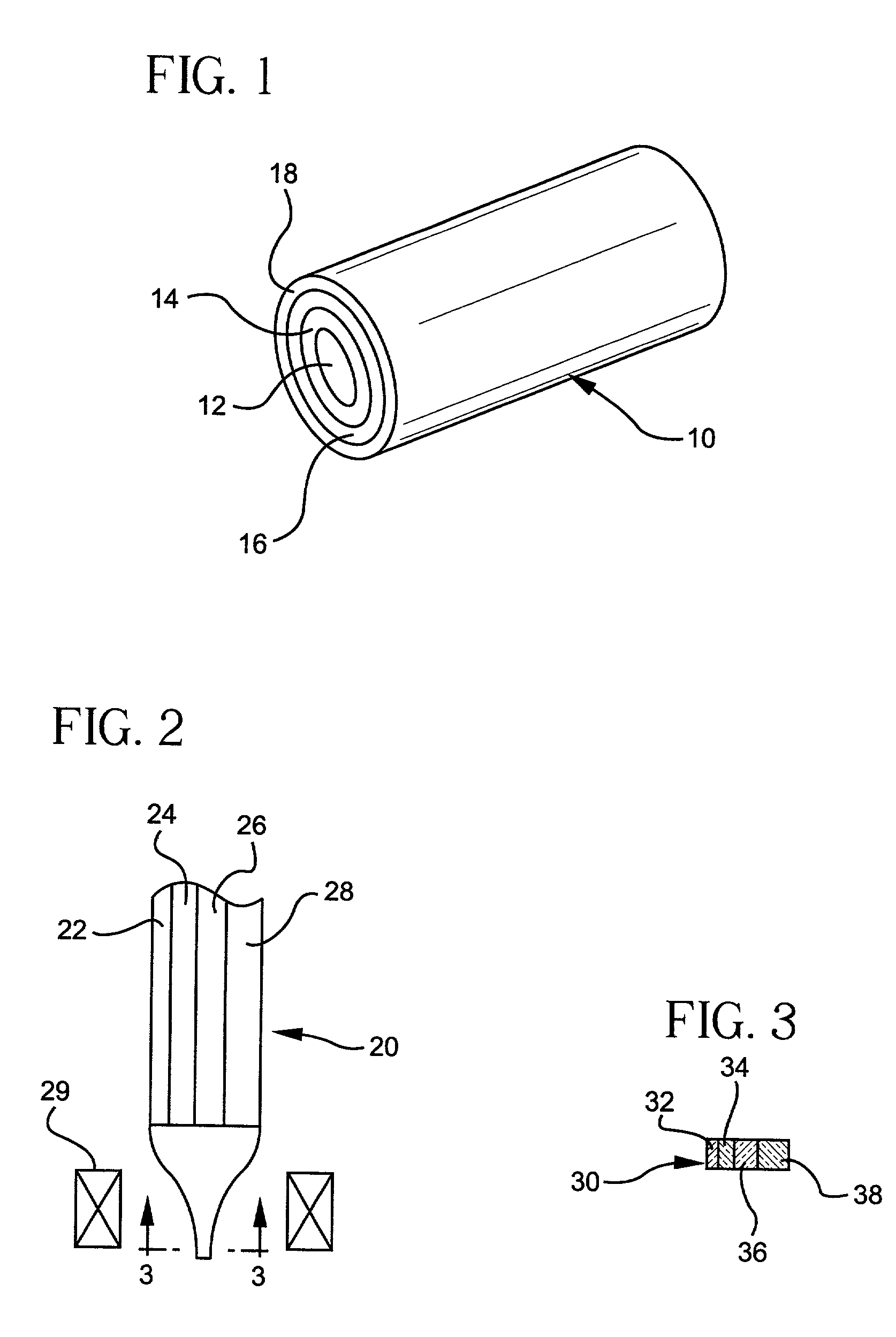
Detectable labels, methods of manufacture and use
a technology of detection labels and labels, applied in the field of detection labels, can solve the problems of high cost, high production cost, and difficulty in manufacturing such miniaturized devices, and achieve the effect of facilitating the attachment and binding of biomolecules, and being easy to manufacture and us
- Summary
- Abstract
- Description
- Claims
- Application Information
AI Technical Summary
Benefits of technology
Problems solved by technology
Method used
Image

Examples
Embodiment Construction
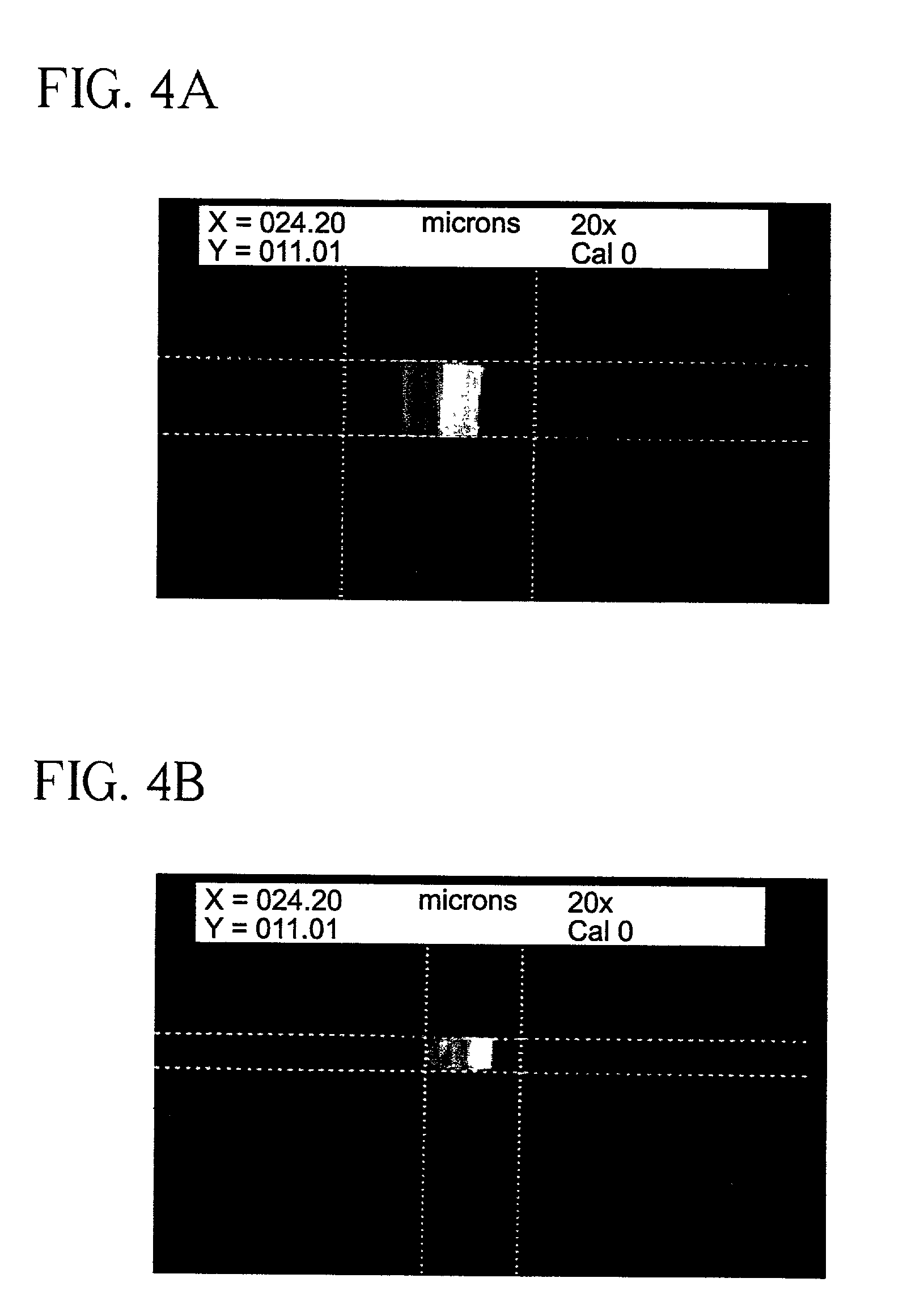
[0047] Tables I and II below show exemplary glass compositions that can be used to make a fluorescent bar code fiber in accordance with one embodiment of the invention. The glass compositions in Table I and Table II were chosen because fluorescent rare earth materials are soluble in these glasses. It will be understood, however, that the present invention is not limited to a particular glass composition, and that the fibers of the present invention could be made from other suitable materials such as polymers or metals.
2 TABLE I Composition (Weight %) 1 2 3 4 SiO.sub.2 50.61 51.22 52.65 52.40 Al.sub.2O.sub.3 14.56 14.73 15.14 15.07 B.sub.2O.sub.3 7.39 7.49 7.70 7.66 MgO 0.64 0.65 0.67 0.67 CaO 3.65 3.70 3.79 3.78 SrO 1.67 1.69 1.73 1.72 BaO 8.24 8.34 8.57 8.54 Eu.sub.2O.sub.3 6.58 0 0 0 Tb.sub.2O.sub.3 0 6.93 0 0 CeO.sub.2 0 0 0.23 0 Tm.sub.2O.sub.3 0 0 0 0.99 Y.sub.2O.sub.3 0 0 4.11 3.79 Sb.sub.2O.sub.3 1.45 0 0 0 F 0.24 0.24 0.24 0.24
[0048] The glass compositions above were melted ...
PUM
| Property | Measurement | Unit |
|---|---|---|
| diameter | aaaaa | aaaaa |
| diameter | aaaaa | aaaaa |
| diameter | aaaaa | aaaaa |
Abstract
Description
Claims
Application Information