Staged assembly of nanostructures

a nanostructure and stage technology, applied in the field of assembly of nanostructures, can solve the problems of difficult assembly of nanostructures, slow and tedious manipulation of individual components necessary in the fabrication of nanostructures, etc., and achieve the effect of precise geometric and spatial positioning of individual components

Inactive Publication Date: 2003-10-23
NANOFRAMES
View PDF2 Cites 175 Cited by
  • Summary
  • Abstract
  • Description
  • Claims
  • Application Information

AI Technical Summary

Benefits of technology

[0028] One object of the staged assembly method of the invention is to fabricate nanostructures in which: a) each assembly unit occupies a specific, predetermined location in the nanostructure; b) multiple nanostructures are assembled simultaneously; and c) all the nanostructures are identical in architecture and assembly unit order. In a preferred embodiment of the staged assembly method of the invention, an initiator unit is immobilized on a substrate and additional units are added sequentially in a procedure analogous to solid phase polymer synthesis. Only a few distinct unit-unit interactions need to be used, since the size and shape of the nanodevice will be defined by the order in which units are added. The staged assembly method of the invention requires far fewer non-cross-reacting complementary pairs of joining elements than self-assembly or auto-assembly. Since the engineering or identification of complementary and non-cross-reacting pairs of joining elements constitutes a major barrier to the design of assembly units, the use of the staged assembly method of the invention represents a significant improvement over self-assembly for bottom-up assembly of nanostructures. Each position in the nanodevice can be uniquely defined through the process of staged assembly, and units of distinct functionalities can be added at any desired position. This system enables massive parallel manufacture of complex nanodevices, and different complex nanodevices can be further self-assembled into higher order architectures in a hierarchic manner.

Problems solved by technology

Assembly of nanostructures presents significant problems, however, because their individual components or subunits are very small.
Manipulation of individual components necessary in the fabrication of nanostructures, even when possible, is slow and tedious.
Manipulation becomes particularly problematic when considering the assembly of complex nanostructures that are made up of a large number of components.
Development of the initial stages leading to an assembler has proven difficult, and a practical implementation of a working assembler may be overly difficult, if not impossible, due to inherent limitations (Smalley, 2001, Of Chemistry, Love and Nanobots, Scientific American 285(3):76-77).
As for self-assembling nanostructures, practical implementations have been thwarted by the need to design components that both have the desired functionalities and exhibit the necessary interactions with neighboring components needed to achieve the self-assembly process.
There is a huge gap between the popular vision of computer nanochips self-assembling by the billions out of a solution of molecular components, and the real, pragmatic problems involved in assembling complex nanodevices.
Crystal size is not readily controllable, and there is nothing to distinguish unique positions within the crystal.
Such uniqueness of component position places significant constraints on the design of components of nanostructures, and raises problems that have not yet been solved for a real system.
The design and fabrication of many joining pairs that interact with highly specific and non-cross-reacting interactions represents a challenge at least as great as the design of the functional elements themselves.
These problems led Whitesides and Love, when they analyzed the advantages and disadvantages of "bottom-up" methods of nanofabrication such as self-assembly, to state that "these methods cannot produce designed, interconnected patterns and are not well suited for building electronic devices" (Whitesides and Love, 2001, The Art of Building Small, Scientific American, 285(3): 39-47).
Such programmed molecular building blocks have the drawback, however, that a large number of distinct components must be designed and synthesized to make true self-assembly of a nanostructure possible.
All these approaches, as discussed below, have their drawback.
The trimeric nature of phage tail fiber proteins (Cerritelli et al., 1996, Stoichiometry and domainal organization of the long tail-fiber of bacteriophage T4: a hinged viral adhesin, J. Mol. Biol. 260(5): 767-80), however, limits the geometry to which they can be adapted in their use in a self-assembly or staged-assembly process.
The limitation of this approach, however, is that the disclosed nanostructures, made of a single, double-stranded, polynucleotide lattice, lack structural rigidity and are subject to enzymatic, chemical and photo-degradation.
Furthermore, the disclosed nanostructures provide only a limited range of spatial geometries.
Whereas the patent discloses the assembly of nanostructures, the disclosed method does not accommodate the non-periodic placement of functional moieties within the assembly.
And while a regularly repeating nanostructure is disclosed, the nanostructure cannot achieve completely defined positions of functionality within the nanostructure.
The drawback of this method, however, is that although the nanoparticles are linked together with well-controlled average distances between them, the method cannot provide for controlled geometry or stoichiometry, since the DNA units that provide the specific complementary binding sites are conjugated to inorganic particles with indeterminate stoichiometry and geometry.
This approach does not appear to allow for forming nanostructures, however, as no method for controlling the assembly process is described that would allow ordering of the components.
The drawback of such an approach, however, is that since inorganics are used to organize these structures, it would be impossible to control the geometry or stoichiometry of the interactions to produce the disclosed nanostructures.
Nevertheless, a major shortcoming of the method disclosed in U.S. Pat. No. 5,712,366 is that the molecular components are designed to spontaneously recognize their nearest neighbors, and these nearest-neighbor interactions can only define a repeating pattern of units.
The repeated use of identical interactions among identical units does not provide, however, for the incorporation of special units possessing specific functionalities into specifically defined positions.
The drawback of the method disclosed in U.S. Pat. No. 6,107,038, however, is that in order to carry out the assembly process, the nanocomponents must be physically manipulated by an electric field and introduced as a plurality of components.
The method does not provide for precisely controlling the distance between spatial zones or the distance between anchors.
This method for depositing chemicals onto surfaces specifically, while controlling their positions electrophoretically, cannot be used for the construction of a three-dimensional nanostructures.
The disclosed methods are limited, however, to regular structures, either finite structures with elements defined by point group symmetries, or regularly repeating structures of indeterminate length in one dimension (e.g., fiber), two dimensions (e.g., thin film) or three dimensions (e.g., crystal).
The drawback of the method disclosed in WO 00 / 68248 is that fusion protein units are assembled into nanostructures by self-assembly and cannot spontaneously recognize where they belong within a larger framework.
The units used in the method are designed only to spontaneously recognize their nearest neighbors, and these nearest-neighbor interactions can only define a repeating pattern.
As discussed hereinabove, the repeated use of identical interactions among identical units does not provide for the incorporation of special units possessing specific functionalities into specifically defined positions.
The drawbacks of such a self-assembly method for building a nanostructure, however, are that it proceeds through bonding of domains (e.g., poly-G) of double-stranded DNA to form superstructures, it does not provide for the incorporation of special units possessing specific functionalities into specifically defined positions and it does not provide a diversity of spatial geometries.
While the publication discloses construction of longitudinal fibers, the length of the fibers formed is not controllable.
Moreover, incorporation of functional moieties into the monomer units, either before or after self-assembly, is not stoichiometric or specific.
The major drawback the method disclosed in WO 01 / 21646, however, is that fusion proteins are assembled into nanostructures by self-assembly, the formation of which is not readily controllable.
As in other self-assembly methods, this method results in the formation of regular repeating structures that lack units at specific or selected positions in the nanostructure.
The drawback of such an approach, however, is that it cannot be used for placing nanoparticles in arbitrary, designed positions in a three-dimensional nanodevice.
A disadvantage of this method, however, is that the flexibility of the incorporated antibody molecule (as opposed to an antibody fragment) would make precise location of the fullerene difficult.

Method used


Image

  • Staged assembly of nanostructures
  • Staged assembly of nanostructures
  • Staged assembly of nanostructures

Examples


example 1

6. EXAMPLE 1

Staged Assembly of Hybrid Pilin Assembly Units

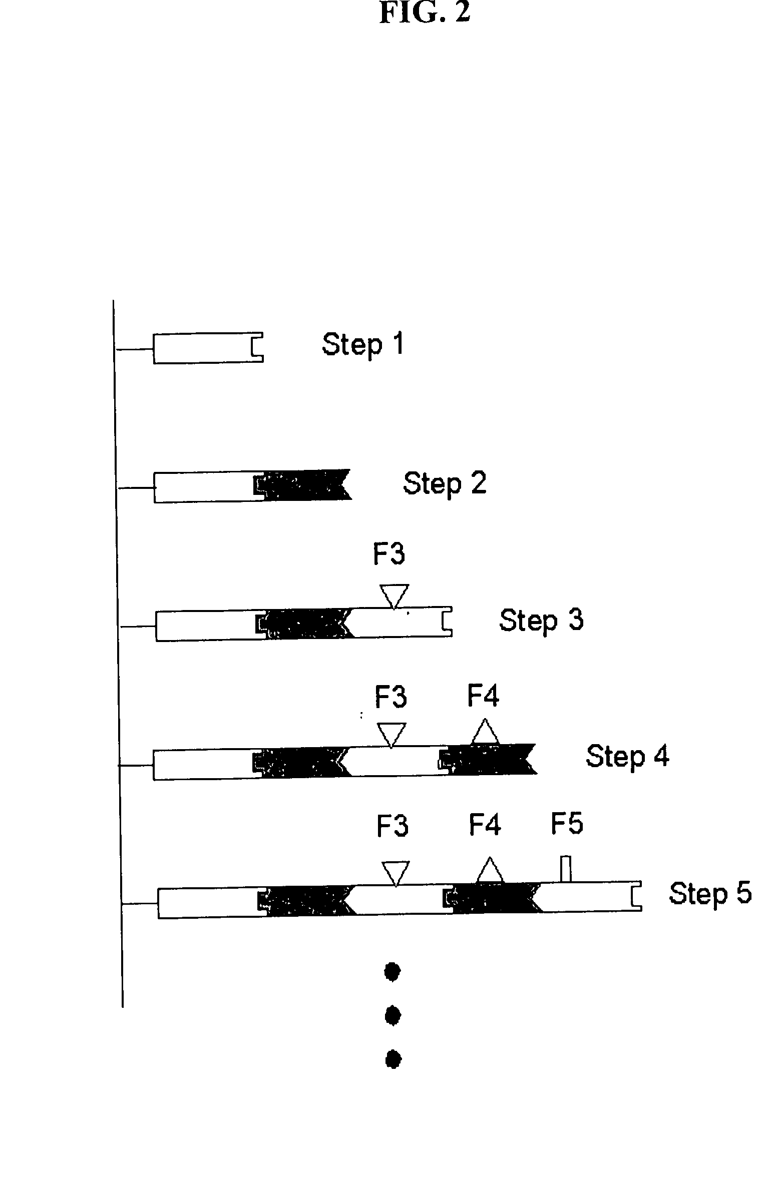
[0406] In this example, hybrid pilin assembly units are constructed using the following steps of the staged-assembly methods of the invention.

[0407] With the immobilized papA and the hybrid proteins engineered as disclosed above, it is possible to assemble a filament comprising five pilin units and having two ras epitopes positioned, one each, on the second and fifth units in the assembly (FIG. 17).

[0408] (1) In the first step, PapA units are immobilized on a solid matrix using methods well known in the art. For example, a biotin moiety may be added to the amino terminus of papA; the papA then incubated in the presence of a surface coated with streptavidin. The very strong interaction of biotin with streptavidin will lead to the immobilization of papA on the surface. Many other methods for the immobilization of a protein on a solid surface are available and well known to those of ordinary skill in the art.

[0409] (2) In the se...

example 2

7. EXAMPLE 2

Staged-Assembly of a Nanostructure Having a Joining Element Comprising a Peptide Epitope

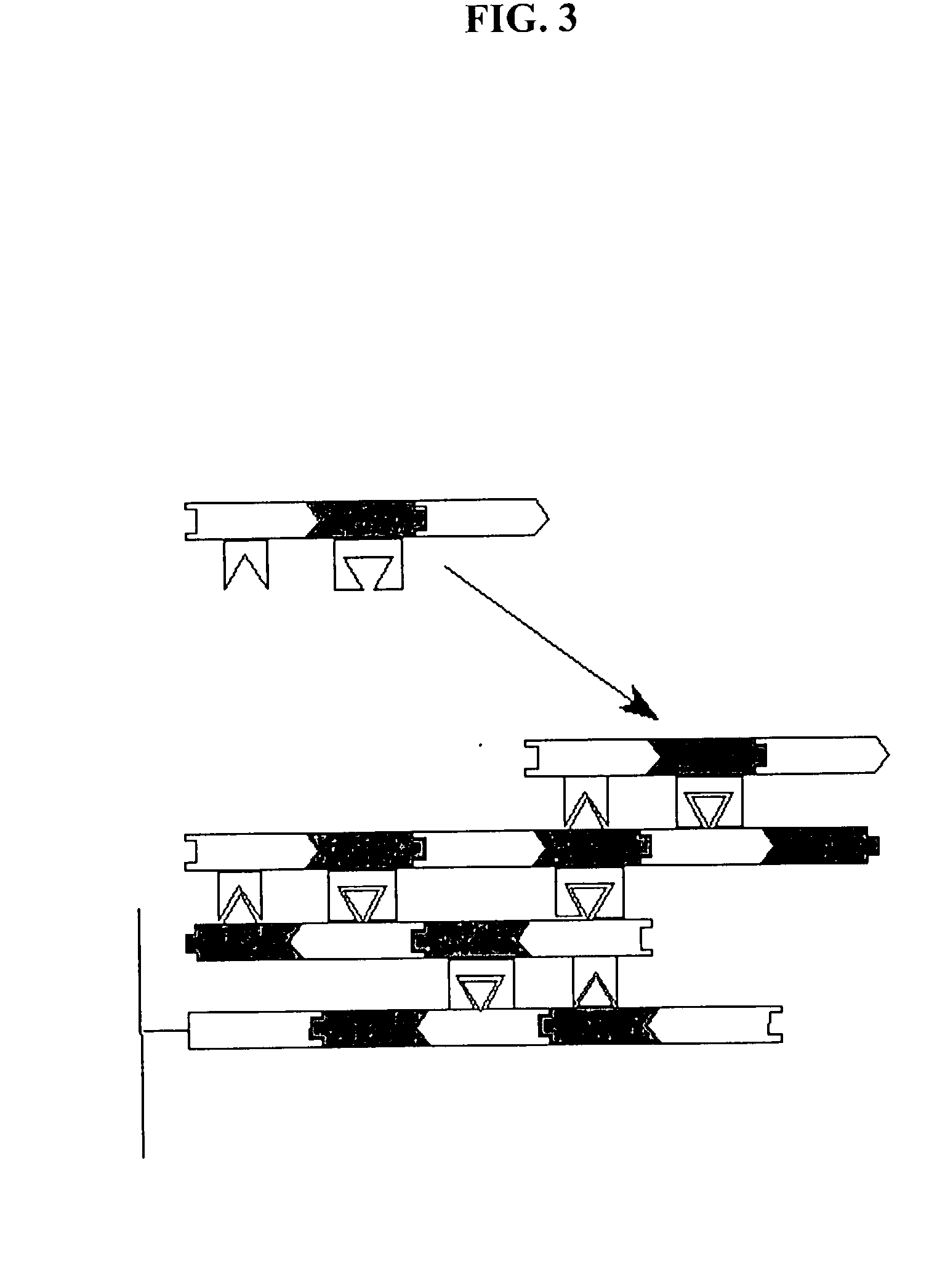
[0414] This example discloses staged assembly using monovalent Fab fragments ("Fab1" and "Fab2,") each with a different peptide epitope fused at their C-terminus (FIG. 7).

[0415] The CDR of Fab1 has specificity for the peptide fused to the C-terminus of Fab2. Likewise, the CDR of Fab2 has specificity for the peptide fused to the C-terminus of Fab1.

[0416] The two joining pairs provide specific interactions between these two assembly units. The first Fab can be immobilized to a solid substrate using standard methods. This surface can then be incubated with a solution containing Fab2 which has fused a peptide exhibiting specificity for Fab1. This incubation will result in the formation of a nanostructure intermediate comprised of one copy of Fab1 (immobilized) and one copy of Fab2. The intermediate can then be incubated against a solution containing Fab1, resulting in the formation of an ...

example 3

8. EXAMPLE 3

Staged Assembly Using Multispecific Protein Assembly Units

[0422] This example discloses an embodiment of the staged assembly methods of the invention that uses multispecific protein assembly units. Permutations and combinations of multispecific protein assembly units may be used for the construction of complex one-, two-, and three-dimensional macromolecular nanostructures, including, for example, the staged assembly illustrated in FIG. 21, which utilizes bivalent and tetravalent assembly units.

[0423] Staged assembly of a nanostructure comprising a four-point junction only requires a minimum of five assembly units and four joining pairs. The five assembly units required include four bispecific and one tetraspecific assembly unit. In this example, the joining pairs employed to join adjacent assembly units are idiotope / anti-idiotope in nature. A minimum of four such idiotope / anti-idiotope joining pairs are needed for staged-assembly in this example.

8.1. Assembly Units

[0424...


PUM

PropertyMeasurementUnit
Fab angleaaaaaaaaaa
pHaaaaaaaaaa
angleaaaaaaaaaa

Abstract

The present invention provides methods and assembly units for the construction of nanostructures. Assembly of nanostructures proceeds by sequential, non-covalent, vectorial addition of an assembly unit to an initiator or nanostructure intermediate during an assembly cycle, a process termed "staged assembly." Attachment of each assembly unit is mediated by specific, non-covalent binding of a single pre-determined joining element of one assembly unit to a complementary joining element on a target initiator or nanostructure intermediate. Each interaction of a joining element is designed such that the joining element does not interact with any other joining element of the assembly unit. Self-association of the assembly unit is therefore obviated: only one assembly unit can be added at a time to a target initiator or nanostructure intermediate.

Description

1. TECHNICAL FIELD[0001] The present invention relates to methods for the assembly of nanostructures and assembly units for use in the construction of nanostructures.2. BACKGROUND OF THE INVENTION[0002] Nanostructures are structures with individual components having one or more characteristic dimensions in the nanometer range (from about 1-100 nm). The advantages of assembling structures in which components have physical dimensions in the nanometer range have been discussed and speculated upon by scientists for over forty years. The advantages of these structures were first pointed out by Feynman (1959, There's Plenty of Room at the Bottom, An Invitation to Enter a New Field of Physics (lecture), Dec. 29, 1959, American Physical Society, California Institute of Technology, reprinted in Engineering and Science, February 1960, California Institute of Technology, Pasadena, Calif.) and greatly expanded on by Drexler (1986, Engines of Creation, Garden City, N.Y.: Anchor Press / Doubleday)....

Claims


Application Information

Patent Timeline
Patent Type & Authority Applications(United States)
IPC IPC(8): B82B1/00B05D3/00B82B3/00C07K14/00C07K14/195C07K16/00C07K19/00C12N15/09C12Q1/68G01N33/68
CPCB82Y5/00C07K14/003C12Q1/68C07K16/005C07K14/195B82B1/00B82B3/0009C12Q1/6806G01N33/53
Inventor MAKOWSKI, LEEHYMAN, PAUL L.WILLIAMS, MARK K.
Owner NANOFRAMES
Why Eureka
Try Eureka