Power amplifying apparatus and radio communications apparatus using same

a technology of power amplifying apparatus and power amplifier, which is applied in the direction of automatic tone/bandwidth control, gain control, amplifier modification to reduce non-linear distortion, etc., can solve the problem of difficult distortion cancellation using a feedback system, inability to achieve desired results with respect to third harmonic distortion attenuation, and large inductan

Inactive Publication Date: 2003-11-20
SONY CORP
View PDF2 Cites 18 Cited by
  • Summary
  • Abstract
  • Description
  • Claims
  • Application Information

AI Technical Summary

Problems solved by technology

In addition, the most significant problem with the conventional power amplifier mentioned above is that because it has such a configuration that the low-frequency signal is reinjected into the drain of the amplification FET 101, a coil with an extremely large inductance needs to be provided as the low-frequency choke inductor 104.
However, when random signals such as digital modulated waves are inputted, the desired results with respect to third harmonic distortion attenuation cannot be achieved due to propagation time delay in the feedback path.
Particularly with respect to signals with a high chip r...

Method used


Image

  • Power amplifying apparatus and radio communications apparatus using same
  • Power amplifying apparatus and radio communications apparatus using same
  • Power amplifying apparatus and radio communications apparatus using same

Examples


first embodiment

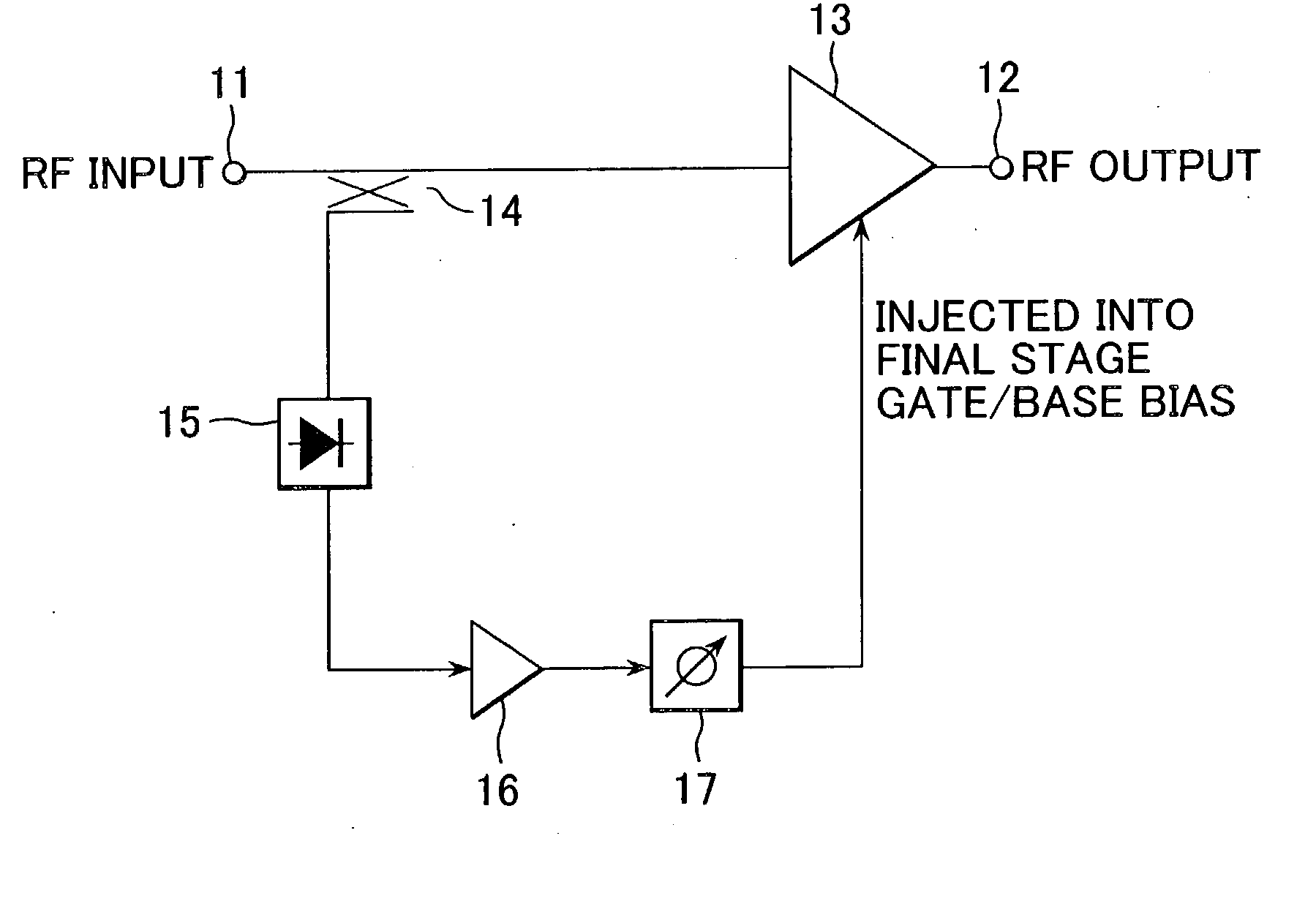
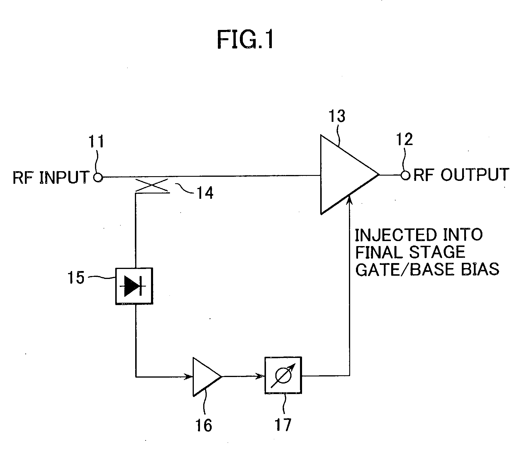
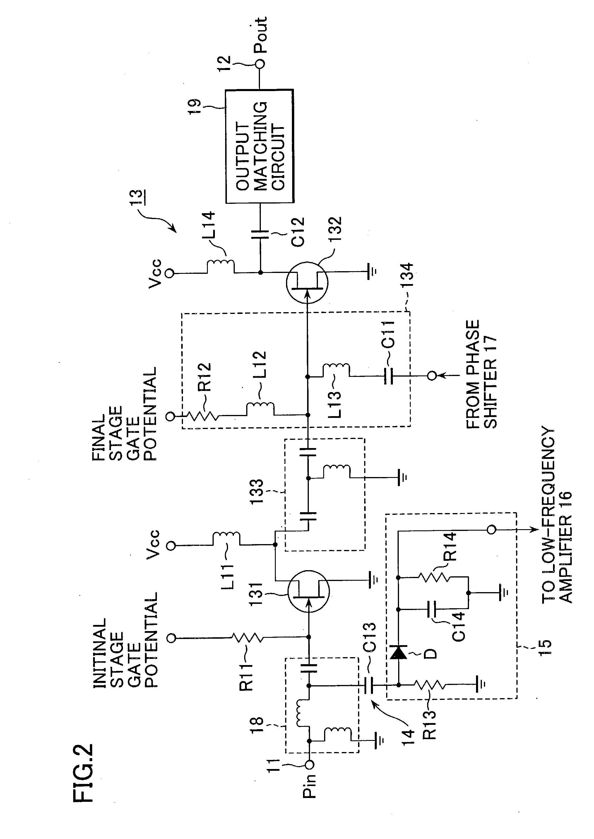
[0045] FIG. 2 is a circuit diagram showing an example of a power amplifying apparatus according to a modification of the first embodiment, and the same reference numerals as those in FIG. 1 are used for equivalent or like parts.

[0046] In FIG. 2, the low-frequency amplifier 16 and the phase shifter 17 shown in FIG. 1 are omitted. In addition, an input matching circuit 18 is connected between the input terminal 11 and the multistage RF amplifier 13 and an output matching circuit 19 is connected between the multistage RF amplifier 13 and the output terminal 12.

[0047] In the present example, the multistage RF amplifier 13 is shown to have a two-stage configuration, and FETs are used as transistors for the multistage RF amplifier 13. In other words, the multistage RF amplifier 13 has an initial-stage FET 131 and a final-stage FET 132. The drain of the initial stage FET 131 and the gate of the final stage FET 132 are connected via an inter-stage matching circuit 133. The gate of the initi...

first modified example

of the First Embodiment

[0064] FIG. 8 is a block diagram showing an example of a configuration of a power amplifying apparatus according to the first modified example of the first embodiment, and like parts that can be found in FIG. 1 are identified with the same reference numerals and characters.

[0065] The power amplifying apparatus according to the present modified example adopts a configuration in which a band-pass filter (or a low-pass filter) 20 is provided between the detector 15 and the low-frequency amplifier 16. The basic operation of the power amplifying apparatus with such a configuration is similar to the operation described in connection with FIG. 1. However, in the power amplifying apparatus according to the present modified example, harmonic components contained in the low-frequency signals outputted from the detector 15 are actively filtered by the band-pass filter (or the low-pass filter) 20, and only low-frequency second-harmonic distortion components are extracted....

second modified example

of the First Embodiment

[0067] FIG. 9 is a block diagram showing an example of a configuration of a power amplifying apparatus according to the second modified example of the first embodiment, and like parts that can be found in FIG. 1 are identified with the same reference numerals and characters.

[0068] Whereas in the first embodiment and the first modified example, the detector 15 for detecting second-harmonic distortion components of low-frequency signals was provided in an RF stage, the present modified example adopts a configuration in which the detector 15 is provided in an IF stage (an intermediate frequency stage), and in which a portion of IF signals are inputted to the detector 15 via a coupler 14A.

[0069] In FIG. 9, a frequency converter 21, a band-pass filter (BPF) 22, a driver amplifier 23 and the multistage RF amplifier 13 are connected in cascade between the input terminal 11 and the output terminal 12. The frequency converter 21 converts IF signals into RF signals by m...


PUM


Abstract

By extracting a portion of RF signals from an input side of a multistage RF amplifier with a detector, and converting extracted signals into envelope signals, low-frequency second-harmonic distortion components are efficiently extracted. Then, the extracted low-frequency second-harmonic distortion components are amplified with a low-frequency amplifier, and phase adjusted with a phase shifter, after which they are injected into a gate or base bias of the final stage of the multistage RF amplifier. As a result, the low-frequency second-harmonic distortion components are converted into third-harmonic distortion due to the non-linearity of transistors, and the third-harmonic distortion thus obtained cancels out the third-harmonic distortion originally present in the multistage RF amplifier.

Description

[0001] The present document claims priority to Japanese Priority Document JP 2002-144224, filed in the Japanese Patent Office on May 20, 2002, the entire contents of which are incorporated herein by reference to the extent permitted by law.[0002] 1. Field of the Invention[0003] The present invention relates to a power amplifying apparatus and a radio communications apparatus using this power amplifying apparatus. More particularly, the present invention relates to a power amplifying apparatus having a distortion compensation function and a radio communications apparatus using such a power amplifying apparatus.[0004] 2. Description of the Related Art[0005] In radio communications apparatuses such as cellular phones which adopt linear modulation systems including CDMA (Code Division Multiple Access) and the like, power amplifying apparatuses with low distortion and high efficiency are required. As a power amplifying apparatus of such sort, a power amplifying apparatus having a distort...

Claims


Application Information

Patent Timeline
IPC IPC(8): H03F1/02H03F1/32H03F3/21H04B1/04
CPCH03F1/0266H04B2001/0441H03F1/3223H03F3/24H03F1/32
Inventor SASHO, NOBORUABE, MASAYOSHI
Owner SONY CORP
Why Eureka
Try Eureka