Image display apparatus, disassembly processing method therefor, and component recovery method

a technology of image display and disassembly processing, applied in the direction of identification means, glass recycling, instruments, etc., can solve the problems of insufficient drainage facilities on sites, insufficient capacity of disposal sites, and inability to discharge hazardous substances

Inactive Publication Date: 2004-01-01
CANON KK
View PDF11 Cites 15 Cited by
  • Summary
  • Abstract
  • Description
  • Claims
  • Application Information

AI Technical Summary

Benefits of technology

[0033] The present invention has been made to solve the above problem, and has as its object to provide a processing method of easily reusing a scrapped FPD.
[0156] According to the present invention, residues on a glass substrate surface can be detected by a simple method, and all the elements other than a glass constituent element can be removed in the step of processing used substrate glass. Consequently, glass can be efficiently reused without any wastes.

Problems solved by technology

In recent years, a shortage of the capacity of disposal sites poses a serious problem, and environmental pollution by hazardous substances also poses a serious problem.
However, rainwater naturally permeates in least controlled landfill sites, and these sites are not equipped with any drainage facility.
This is because, if lead is mixed in panel glass by a predetermined amount or more, a browning phenomenon occurs, and the lead-containing glass cannot be reused as a raw material of the panel glass.
Even if many elements are arranged on a substrate at a high density, problems such as thermal melting of the substrate hardly arise.
In addition, the response speed of the thermionic cathode element is low because it operates upon heating by a heater, whereas the response speed of the cold cathode element is high.
If the rear plate and face plate are made thick, this increases the weight of the image display apparatus, and generates distortion and disparity of an image when viewed diagonally.
Flat panel displays having this structure are expected to abruptly increase in size and production.
[Problem 3] When a flat display is scrapped owing to generation of defects during the manufacture or upon the lapse of a service life, the entire display is shredded and scrapped, which increases the scrap amount.
[Problem 4] When a flat display is scrapped owing to generation of defects during the manufacture or upon the lapse of a service life, the entire display is shredded and scrapped, which is economically undesirable because the constituent material contains a relatively high-cost material.
Especially, the panel uses many spacers, and the manufacture of spacers requires a high manufacturing cost and long time because glass must be formed into thin pieces and conductive films must be formed.
As described above, the spacer is a thin plate and formed from a glass substrate, and may be damaged while a display is dismantled.
[Problem 5] Conventionally, rare-earth elements have hardly been recovered from a display apparatus scrapped after use.
This is because (1) the amount of rare-earth elements used per display apparatus is very small, and the recovery is difficult, (2) rare-earth elements are used not as single substances but as compounds or alloys, and the separation cost is high, and (3) relatively low-cost imported rare-earth elements can be acquired at lower cost under the influence of the strong yen.
On the other hand, a face plate from which fluorescent substances are recovered loses almost all the smoothness of the inner surface.
However, this method is no longer effective because least controlled landfill sites are being saturated.
Moreover, acid treatment is wet treatment, and is not preferable in terms of the cost and work environment.
In returning to the atmospheric pressure, as the pressure difference from the internal pressure of the airtight container is larger, a larger amount of gas such as air often abruptly flows into the airtight container to damage the interior of the airtight container or destruct the airtight container.
This may unexpectedly destruct the airtight container to scatter fragments, which is not preferable in terms of safety.
However, to maximally reuse each member of an image display apparatus, the destruction not only increases wastes such as garbage in terms of resource conservation, but also wastes energy and labor.
The destruction greatly damages the atmospheric pressure-resistant constituent members, and the destructed members damage and destruct the interior of the airtight container of the image display apparatus to inhibit reuse of these members.
[Problem 7] When a flat display is scrapped owing to generation of defects during the manufacture or upon the lapse of a service life, the entire display is shredded and scrapped, which poses an environmental problem, and is not economically preferable because the constituent material of an element includes a relatively high-cost material.
The spacers require a high manufacturing cost and long time because glass must be shredded into thin pieces and conductive films must be formed.
This method, however, must scan the entire surface of a member to be inspected, and becomes cumbersome for many targets to be inspected such as glass cullets.
Inspection target objects are limited, quantitative detection is impossible, and the method is difficult to apply.
[Problem 9] A technique of disassembly processing for recycling a flat display panel is being developed, and conventional related arts cannot be directly adopted.
This technique cannot be applied to disassembly of a flat display panel.
However, practicing this method on a large scale requires a large amount of aqueous solution for dissolving lead and a large amount of water for the subsequent cleaning step.
This increases the processing cost.
[Problem 11] Rare-earth elements have hardly been recovered from a display scrapped after use.
This is because (1) the amount of rare-earth elements used per display is very small, and the recovery is difficult and has not been automated, (2) rare-earth elements are used not as single substances but as compounds or alloys, and the separation cost is high, and (3) relatively low-cost imported rare-earth elements can be acquired at lower cost under the influence of the strong yen.
However, practicing this method on a large scale requires a large amount of aqueous solution for dissolving lead and a large amount of water for the subsequent cleaning step must be prepared.
Further, to heat and flow a solution, large energy must be applied.
Thus, the thin film may be difficult to completely separate from substrate glass.

Method used


Image

  • Image display apparatus, disassembly processing method therefor, and component recovery method
  • Image display apparatus, disassembly processing method therefor, and component recovery method
  • Image display apparatus, disassembly processing method therefor, and component recovery method

Examples


example 1-1

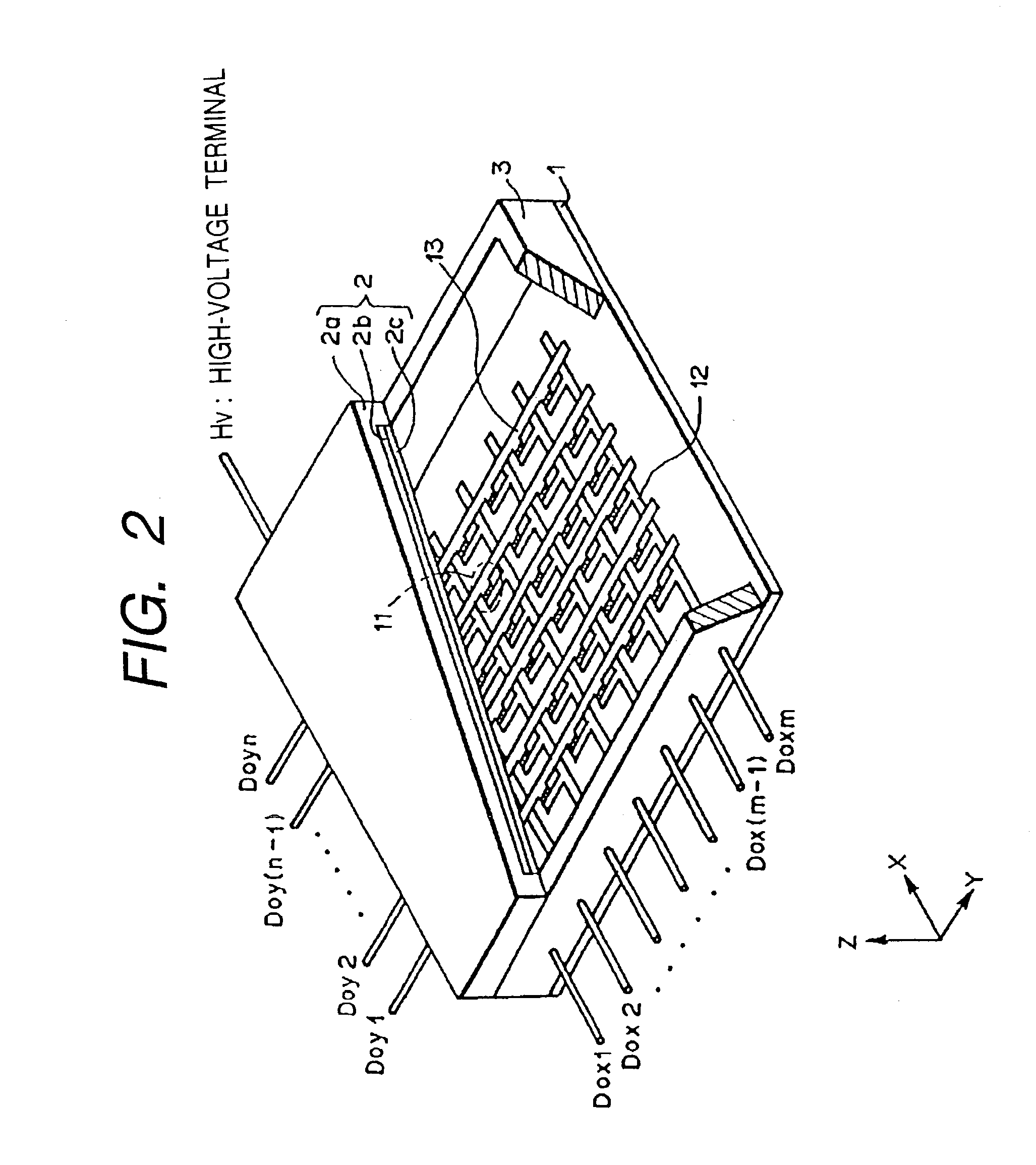
[0258] A surface-conduction type electron source display (SED) of matrix driving scheme as shown in FIG. 2 was disassembled. This SED has a panel structure containing spacers as shown in FIG. 1.

[0259] In accordance with the flow chart of disassembly processing for an FPD device in FIG. 4, the SED was extracted from the housing of the SED device, and accessory wiring lines and terminals were removed. Then, the vacuum in the SED was canceled, and the exhaust pipe was detached. The exhaust pipe was processed and reused as lead-containing glass.

[0260] The SED was image-sensed with a video camera, and its image was captured by an image processing apparatus. A region of the image where frit glass was applied can be recognized as a darker region than the remaining portions. The image was binarized to measure the area of the region where frit glass was applied.

[0261] Disassembly pre-processing steps (1) to (5) were executed. The flat panel display was removed from the housing of the flat pa...

example 1-2

[0270] A surface-conduction type electron source display (SED) of matrix driving scheme as shown in FIG. 2 was disassembled. Steps up to the step of setting the cutting lines A-A, A'-A', B-B, and B'-B' are the same as in Example 1. The SED was scratched with a hard metal roller along the SED cutting lines. Subsequently, the scratched portions were sequentially heated with a gas burner in which oxygen was added to city gas. As a result, the glass was cut along the cutting lines, and the SED was divided into a frame portion 3, face plate 2, and rear plate 1. The subsequent steps were the same as in Example 1-1.

[0271] Since Example 1-2 does not use any grinding solution, members can be easily recovered and reused.

embodiment 2

[0272] [Embodiment 2]

[0273] Embodiment 2 of the present invention will be explained in detail below with reference to the accompanying drawings.

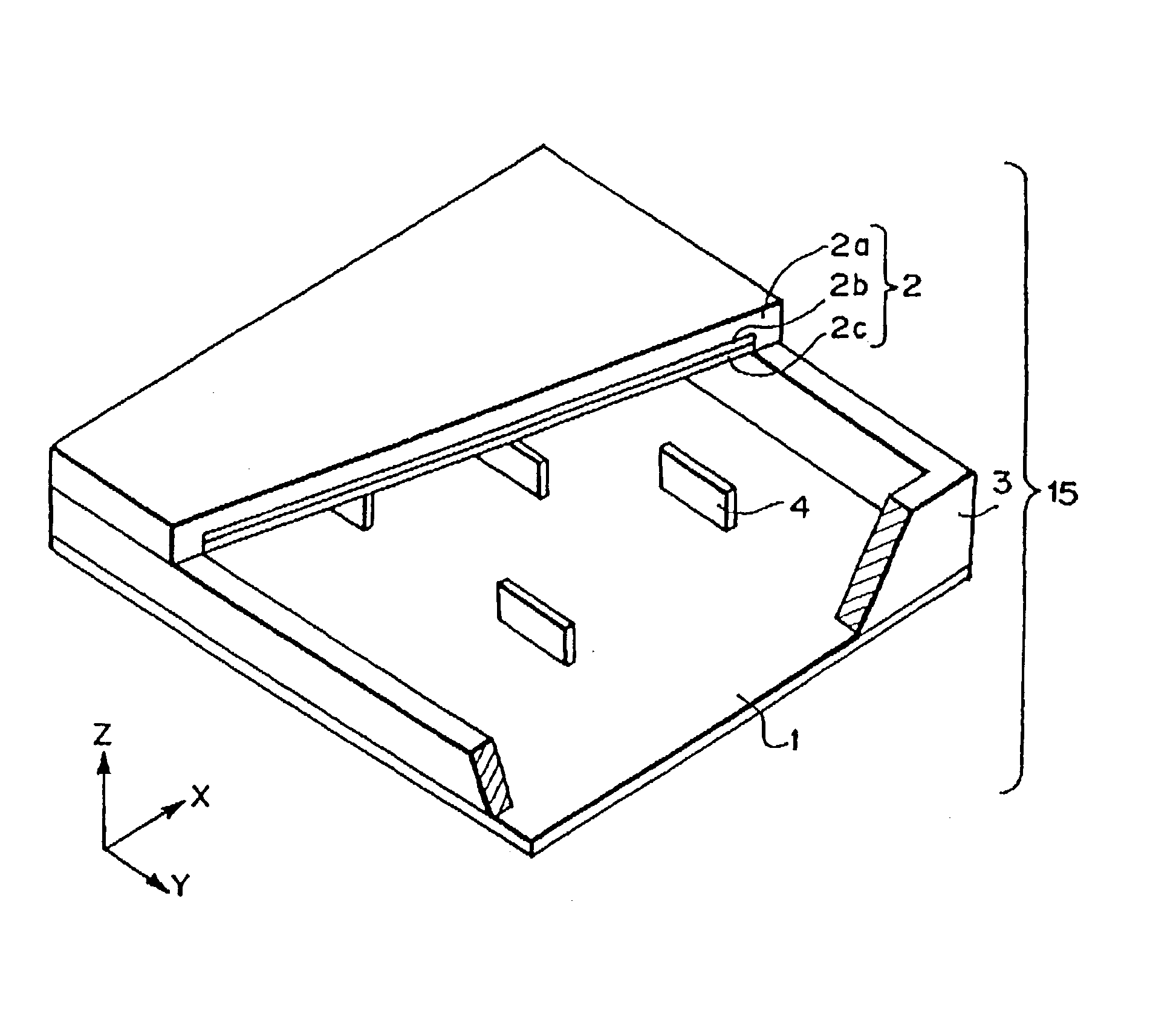
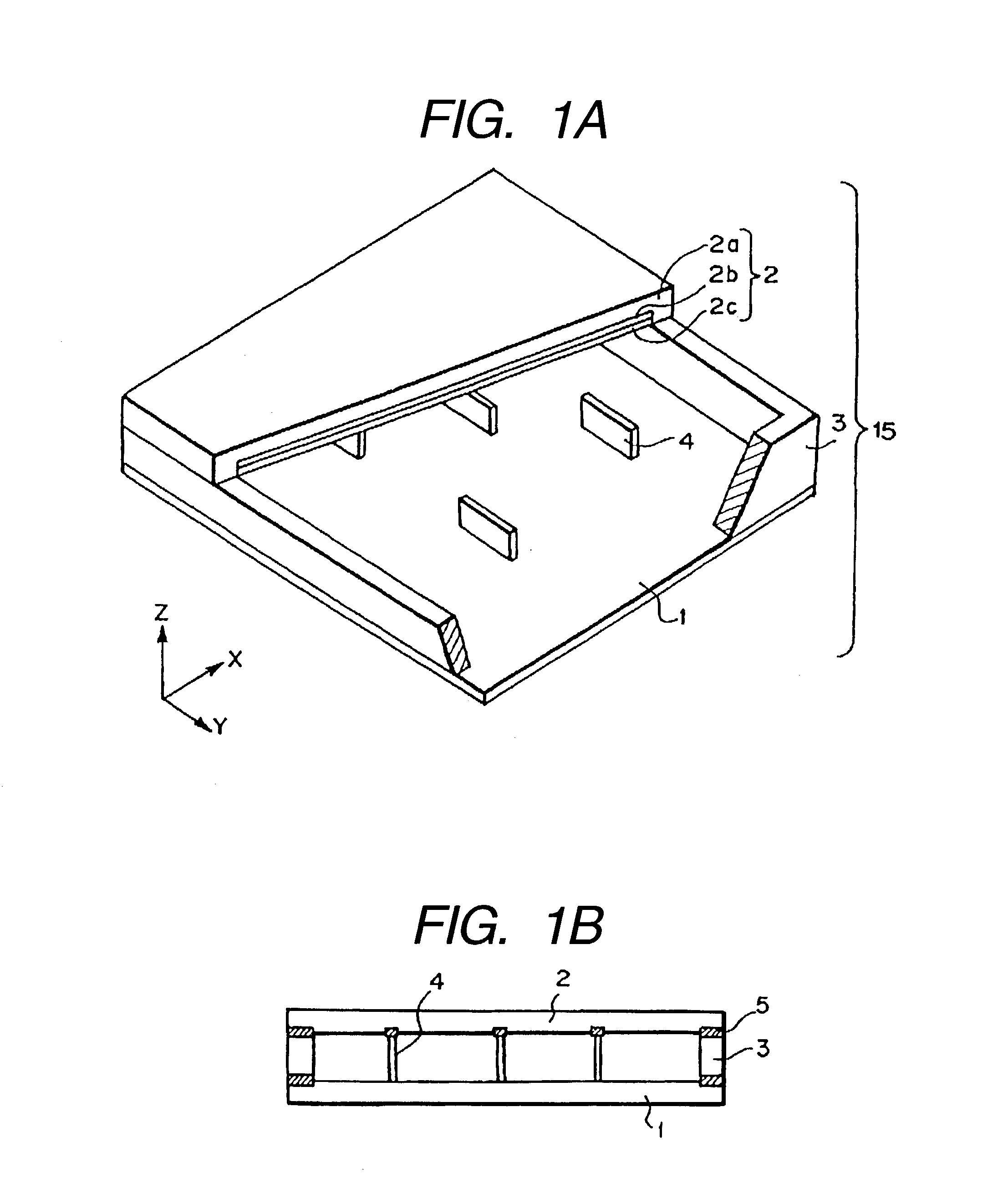
[0274] FIG. 5 is a flow chart showing an FPD disassembly processing method according to this embodiment of the present invention. This embodiment will exemplify disassembly processing for an FPD having spacers, as shown in FIG. 1.

[0275] In FIG. 1, reference numeral 1 denotes a rear plate; 2, a face plate; 3, a frame; and 4, spacers. Lead-containing frit glass 5 is used at each joint portion shown in black in FIGS. 1A, 1B, and 2. The spacers 4 are bonded to either one of the face plate 2 and rear plate 1 or both of them. In this embodiment, the spacers 4 are bonded to only the face plate 1.

[0276] Examples of the materials of the rear plate 1, face plate 2, and frame 3 are silica glass, glass containing a small amount of impurity such as Na, soda-lime glass, and glass prepared by depositing SiO.sub.2 on soda-lime glass by, e.g., sputtering. On...


PUM

PropertyMeasurementUnit
thicknessaaaaaaaaaa
softening temperaturesaaaaaaaaaa
melting pointaaaaaaaaaa

Abstract

To reuse glass used in a flat panel display, processing suitable for global environment such as processing of separating a lead component must be realized. A disassembly processing method for a flat panel display having a structure in which a face plate and rear plate mainly containing glass are airtightly joined via a frame with frit glass is characterized by including the step of separating the face plate and rear plate joined with the frit glass. The separation step is characterized by separating the face plate and rear plate by cutting, dissolution, or melting.

Description

[0001] The present invention relates to, in order to protect the global environment, a method of disassembling for scraping a flat panel display constituted by airtightly joining via a frame with frit glass or the like two substrates, i.e., a face plate (front glass substrate) and rear plate (rear glass substrate) mainly containing glass, a method of reusing a flat panel display, separating and recovering lead as a hazardous metal element among metal elements used for the flat panel display, and effectively reusing other noble metal elements and rare-earth elements, a method of dismantling an image forming apparatus welded with frit glass and recycling its face plate and rear plate, a method of recovering and reusing a spacer, a method of recovering fluorescent substances from a flat display apparatus or CRT (Cathode Ray Tube) for emitting light by irradiating a fluorescent substance-coated portion with an electron beam or ultraviolet ray, a display apparatus manufacturing method, a...

Claims


Application Information

Patent Timeline
Patent Type & Authority Applications(United States)
IPC IPC(8): B09B3/00B03B9/06B09B5/00C22B3/04C22B7/00G02F1/13G09F9/00H01J9/50H01J9/52
CPCB03B9/062B09B5/00H01J2329/00H01J2201/3165H01J9/52Y02W30/60Y02W30/82H01J9/50
Inventor NOMA, TAKASHIKOBAYASHI, TOYOKOMOTOI, TAIKOTAKASE, HIROMITSUMIURA, NAOKOKOBAYASHI, SHIN
Owner CANON KK
Why Eureka
Try Eureka