
Spectroscopy illuminator with improved delivery efficiency for high optical density and reduced thermal load

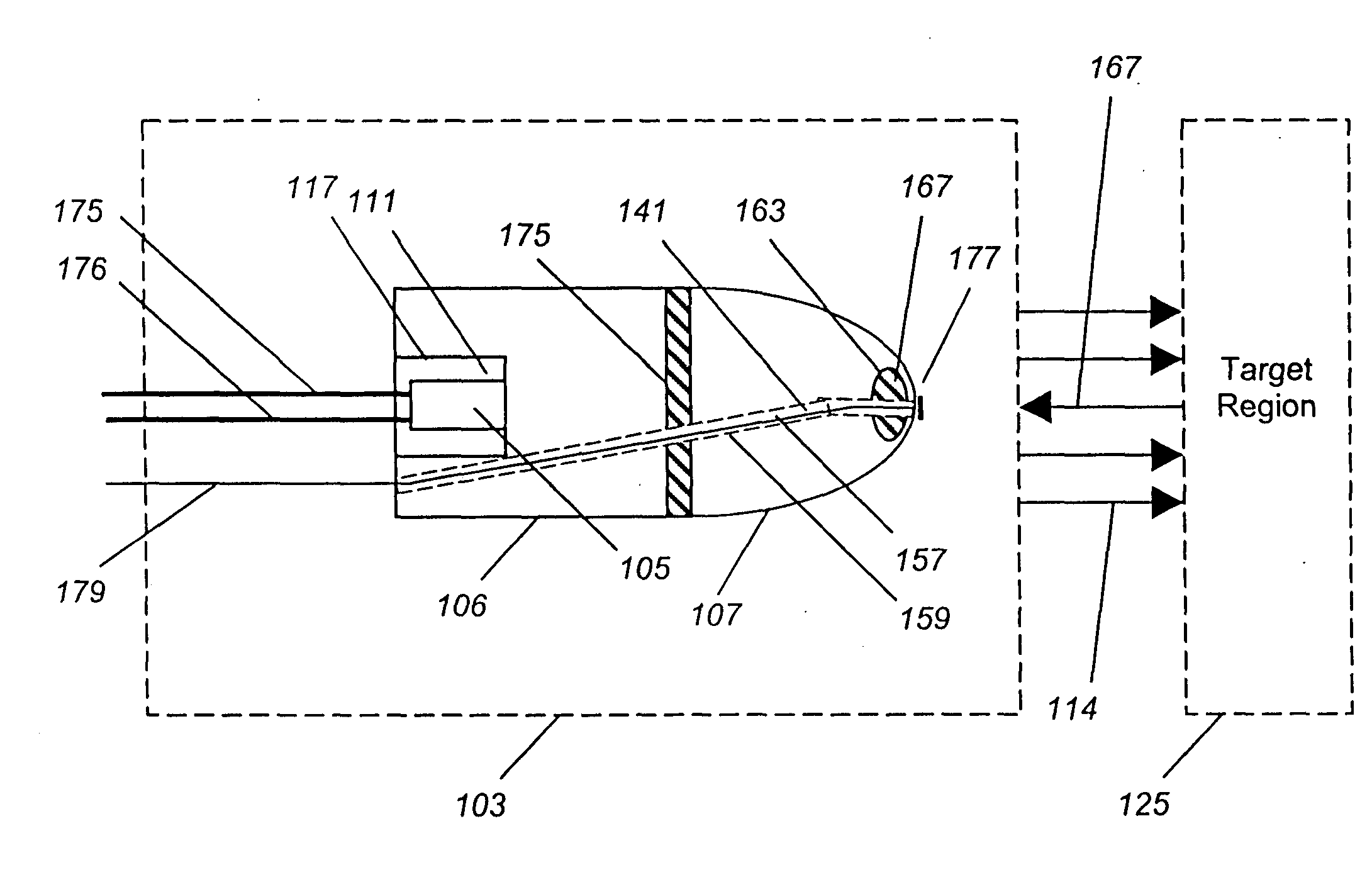
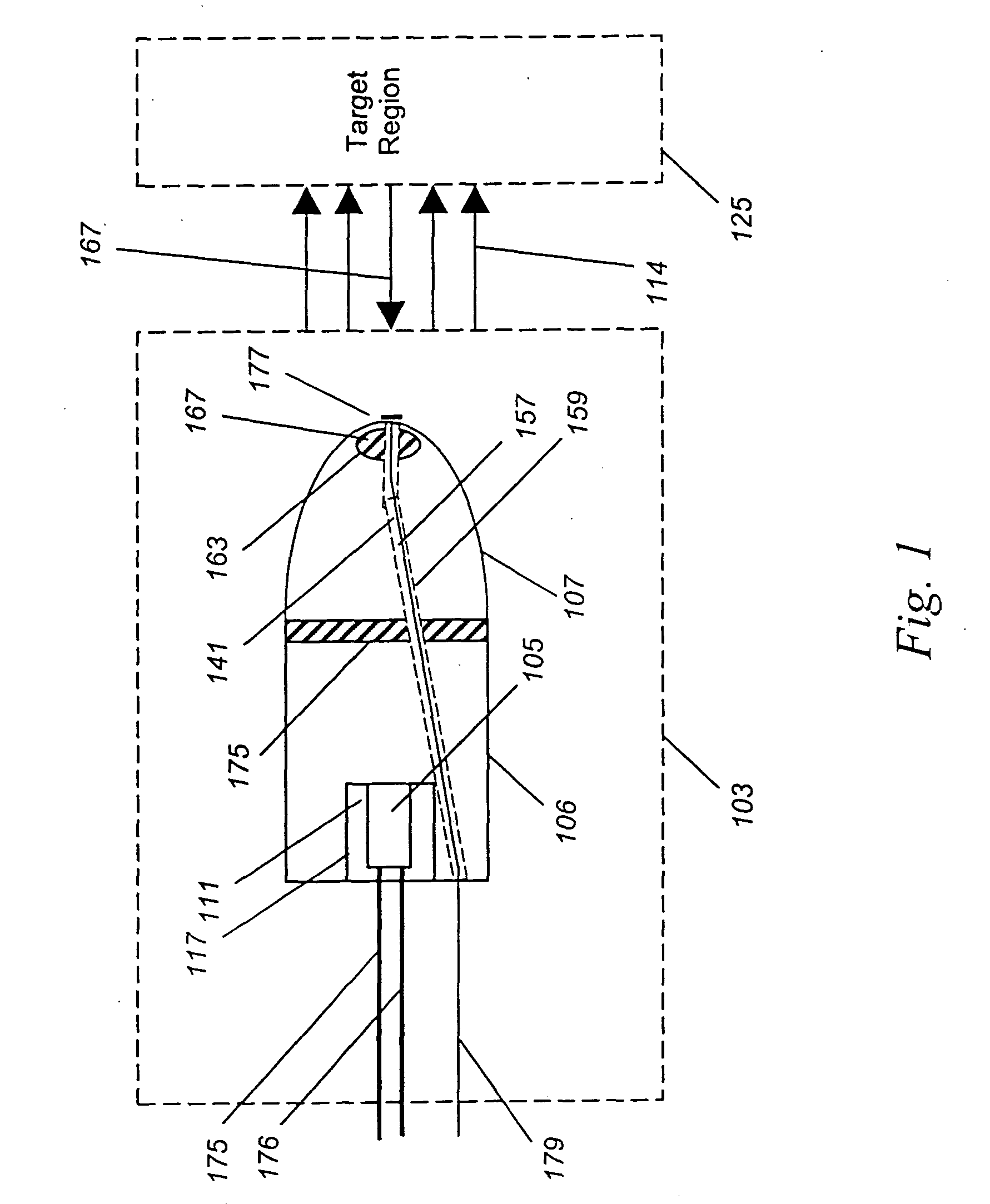
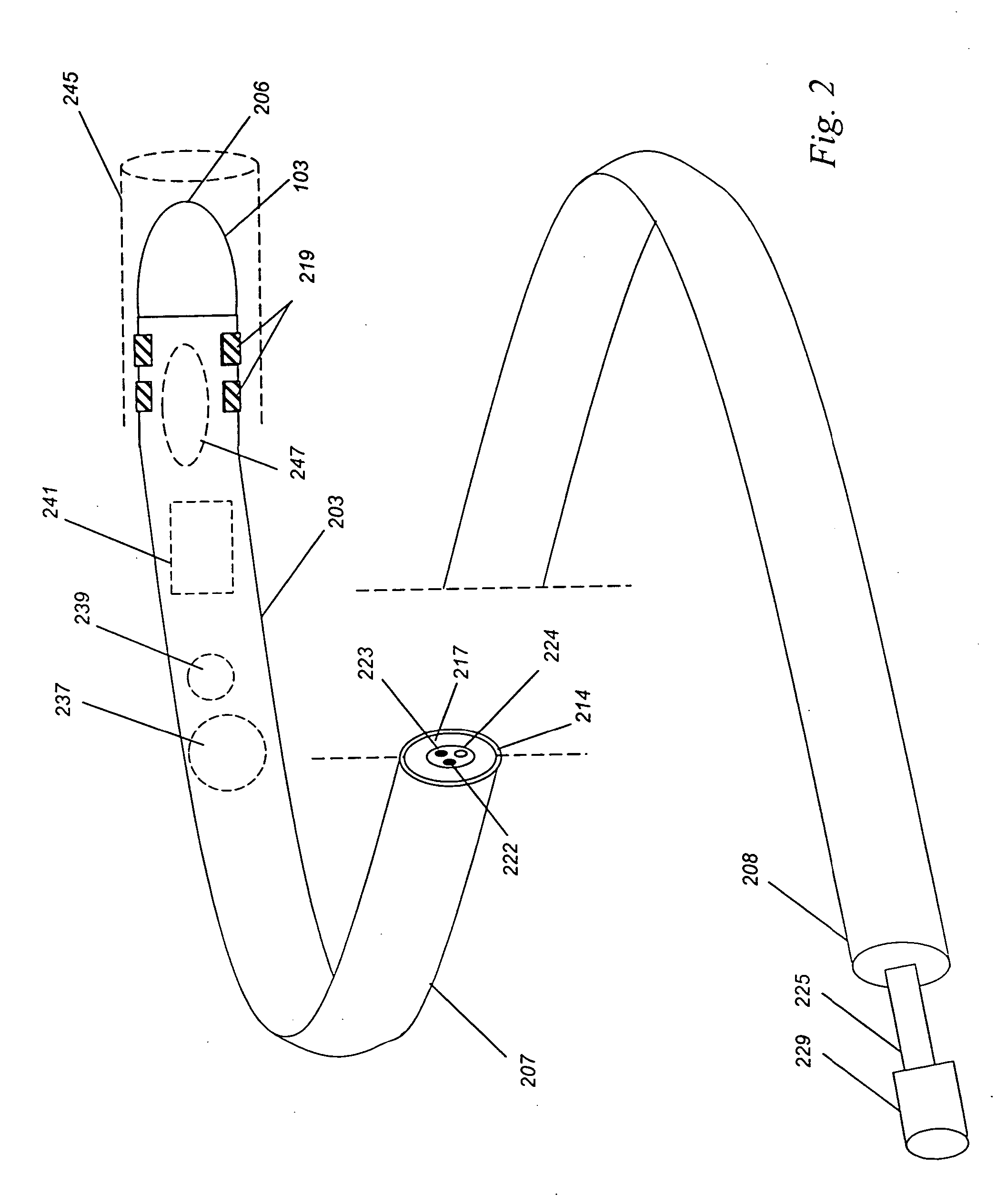
a technology of high optical density and illuminator, which is applied in the direction of spectroscopy diagnostics, optical radiation measurement, instruments, etc., can solve the problems of wasting a large proportion of the power supplied to them as heat and unusable wavelengths of light, rendering inefficient any attempt to direct their light either onto spectroscopy samples, and achieving high efficiency delivery. , the effect of reducing power consumption and/or heat production

Inactive Publication Date: 2004-02-26
J FITNESS LLC
View PDF19 Cites 60 Cited by
  • Summary
  • Abstract
  • Description
  • Claims
  • Application Information

AI Technical Summary

Benefits of technology

"The present invention provides an improved illuminator for spectroscopic analysis that is more efficient in delivering light to a sample, resulting in better illumination and reduced heat production. The design features a high-efficiency light source, such as a phosphor, and specialized optics to improve the delivery of light to the sample. The illuminator can be integrated into small probes and devices, and can be powered by batteries for complete electrical separation. Overall, the invention allows for improved efficiency and stability in spectroscopic analysis, and can be used in a variety of applications."

Problems solved by technology

However, such traditional light sources have significant native disadvantages, including that: (a) they produce their light rather inefficiently, wasting a large proportion of the power supplied to them as heat and unusable wavelengths of light.
This is a drawback in devices where significant local heating (such as medical devices in contact with tissue) or high power consumption (such as battery operated devices for field use) are undesirable or unacceptable, and (b) they emit light over a wide spherical angle from non-point sources, rendering inefficient any attempts to direct their light either onto spectroscopy samples (such as living tissue) or into optical delivery systems (such as fibers coupled to test samples), which in turn further raises heat production and power consumption for any desired level of sample illumination.
First, with specific regard to the production of large amounts of heat, conventional bulbs are inefficient at best.
This conversion efficiency rises to only 14% for so-called high-output halogen lamps (though the improved efficiency results in accelerated drift and bulb aging).
Such poor conversion efficiencies result in a high degree of unwanted thermal output, making conventional bulbs run hot, and in turn preventing close illumination of the sample and often relegating bulb-based light sources into fiber-coupled hot, external, fan-cooled boxes.
Further, because a filament has a length and width, the light can no longer be focused to a point.
This broad spatial emission typically makes a direct coupling of light from a conventional bulb onto a sample, or into an optical guide, inefficient.
The less compact a lamp's source, the more difficult it becomes to focus and guide its light.
This is especially true for UV fluorescent lamps, where focusing losses are far higher than for a halogen bulb.
Further, the surface temperature of a halogen bulb often exceeds 120.degree. C., making a close approximation of a hot bulb and sample not wise or practical in many cases, especially if the sample is living or fragile.
Moving the sample away from the bulb, in order to spare the sample from heating, only worsens the inefficiencies described above.
Nor is the situation improved by separating the bulb and sample using optical fiber.
All told, when taking into consideration both of the above limitations, the poor conversion efficiency of energy to light and the poor transfer efficiency of light to the sample, only 0.0003% of the energy flowing into the 1 cm bulb discussed above ends up converted to visible light, captured, and successfully transmitted by a fiber to a tissue sample, for more than 99.9997% of the total light wasted.
These limitations of conventional sources are apparent in the art.
Several schemes for reducing heat production or for transmitting light to a sample are known (e.g., such as light conducting rods in U.S. Pat. No. 5,974,210), but none with the purpose of improving the efficiency of delivery, nor are these sources specifically designed to operate as cool spectroscopic illuminators with high delivery efficiency.
These systems typically completely ignore the complex issues of broadband illumination source design, suggesting only that known or existing light sources can be used rather than proposing improved illumination sources, and none of these systems consider specifically design issues regarding design and deployment of broadband optical light sources, especially with regard to conversion efficiency, source efficiency, and heat transfer to the sample, nor do they propose any specific or novel high delivery efficient optical sources.
Therefore, all of the above illumination systems and methods suffer from one or more limitations noted above, in that they are either narrow band emitters (such as lasers or filtered spectra), they are not configured to deliver light with a high efficiency, they have obligatory high local heating of the sample, they couple relatively poorly between the bulb and tissue or sample, they are not appropriate to be placed in close proximity to samples, and / or they ignore or omit design considerations regarding illumination efficiency and density, and thus fail to reliably provide an improved illumination source for the performance of spectroscopy in thermally sensitive samples, such as living tissues, or in spatially constrained geometries, such as through fibers and needles.
A delivery-optimized, reduced heat, high-density illuminator for real-time in vivo spectroscopic applications has not been taught, nor has such a tool been successfully commercialized.

Method used


Image

  • Spectroscopy illuminator with improved delivery efficiency for high optical density and reduced thermal load
  • Spectroscopy illuminator with improved delivery efficiency for high optical density and reduced thermal load
  • Spectroscopy illuminator with improved delivery efficiency for high optical density and reduced thermal load

Examples


example 1

[0085] Improved Delivery Via Improved Conversion Efficiency

[0086] One method to improve effective delivery efficiency is to improve the conversion efficiency--that is, to reduce the amount of power needed to produce a given amount of usable light.

[0087] In order to evaluate the impact of design considerations, we modeled the expected improvement in the efficiency of light delivery achieved by altering various aspects of an illumination source design, and then verified our model data using experiments. This model incorporated known features of light generation from tungsten fiber lamps with and without halogen recycle, the transmission characteristics of certain optical fibers, known general characteristics of broadband light emitting diodes (LEDs), and each aspect of the model was tested in the laboratory to confirm agreement of the predictions to those of measured results.

[0088] First, we considered a high efficiency halogen light bulb free-space coupled to a tissue sample--that is...

example 2

[0106] Measurement Using LED and Bulb-Based Probes

[0107] In order to test the validity of the data generated using the model shown in Example 1, we constructed two working probe types, one set using a halogen bulb and a second set using a white LED. Light incident on a tissue phantom was then measured using a silicon-based photodiode system (EXFO, model FOT-50, Quebec, Canada).

[0108] In these measurements, the skin was illuminated using the 15W halogen bulb and the 250 mW white light LED described in the preferred embodiment. Light returning from the skin was collected using a 3.5 mm diameter circular aperture and measured in overall intensity from 400 nm to 1100 nm.

[0109] Results for in-band free-space illumination are shown in Table 3, below:

3TABLE 3 Measured Broadband Free-Space Coupling For Bulb vs. White LED. Trans. Max Thermal Type of1 cm Field Bulb Load (mW Illuminator Current Voltage Power Intensity Temp Heat / Source (mA) (V) (mW) (mW) (.degree. C.) Light / cm.sup.2) Halogen 1...

example 3

[0112] Improved Delivery Via Improved Transfer Efficiency

[0113] An alternative method for improving the net efficiency of light delivery is to improve the coupling of the light source to the sample, measured by transfer efficiency.

[0114] For this example, we considered again a bright halogen projection-type bulb, too hot to put directly next to a sample such as tissue, and in this case even too hot to be safely placed into the handle or tip of a device such as a medical probe.

[0115] One way to get around the heat issue is to fiber-couple the bulb to the sample, thus removing the inefficient and hot light emitter from the vicinity of the sample. As the conversion efficiency of a high-efficiency halogen bulb is difficult to modify, improving the delivery efficiency represents an approachable way for increasing the net transfer efficiency.

[0116] As noted, the best coupling of light would occur in theory if the fiber could be placed in contact with the filament itself, as this is where ...


PUM


Abstract

An improved illuminator for generating broadband light, and for delivering the light to a sample with an improved delivery efficiency, for higher optical density and / or reduced thermal transfer, than achieved with conventional halogen bulb sources. The illuminator enables spectroscopic analysis in thermally-sensitive or spatially-constrained environments. A phosphor-coated broadband white LED and integrated collimating optics produces a continuous, collimated broadband light beam from 400 nm to 700 nm, which is then transmitted through space to a sample region, such as a living tissue in vivo. A method and system for measuring oxigeneration of mucosal or subsurface tissue is also described.

Description

[0001] The present invention relates to illumination devices and systems for providing a high efficiency of broadband light delivery to thermally-sensitive or spatially-constrained environments, and more particularly relates to the embedding of a light source comprised of a white, conversion-efficient, narrow-angle, light emitting diode with integrated collimating and light collection optics into a medical catheter for indwelling gastrointestinal placement for the purpose of performing real-time in vivo tissue oxygenation measurements of mucosal surfaces via visible wavelength optical spectroscopy, thus avoiding some of the cost, risk, light level limitations inherent in conventional illuminator systems.[0002] The traditional broadband light sources for optical spectroscopy in the near UV, visible, and / or near-infrared wavelengths are the fluorescent, incandescent, and arc-lamp bulbs. Typically, spectroscopy bulb is optically coupled to the test sample via gratings, lenses, fibers, ...

Claims


Application Information

Patent Timeline
Patent Type & Authority Applications(United States)
IPC IPC(8): A61B1/06A61B1/00A61B5/00
CPCA61B5/0075A61B5/0084A61B5/14558G01N2201/062A61B5/412A61B5/42G01J3/10A61B5/1459A61B1/00165
Inventor BENARON, DAVID A.PARACHIKOV, ILIAN H.
Owner J FITNESS LLC
Learn More