Negative electrode for lithium secondary battery, method for preparing negative electrode for lithium secondary battery and lithium secondary battery
a secondary battery and negative electrode technology, applied in the manufacturing process of electrodes, cell components, impregnation manufacturing, etc., can solve the problems of deterioration of current collection characteristics (current collectability), etc., to improve current collectability, improve internal strength of electrodes, excellent charge and discharge cycle characteristics
- Summary
- Abstract
- Description
- Claims
- Application Information
AI Technical Summary
Benefits of technology
Problems solved by technology
Method used
Image
Examples
experiment 1
Preparation of Negative Electrode
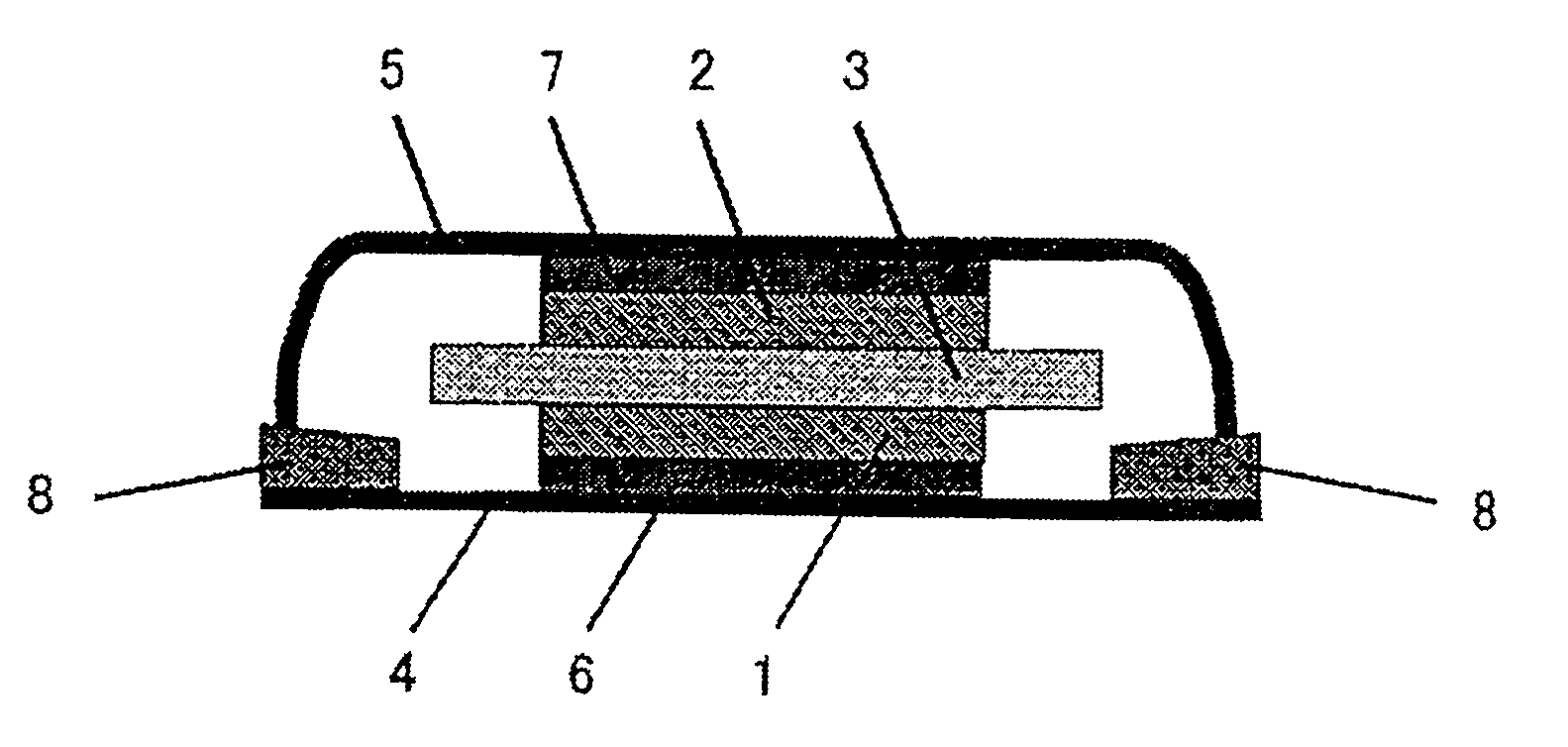
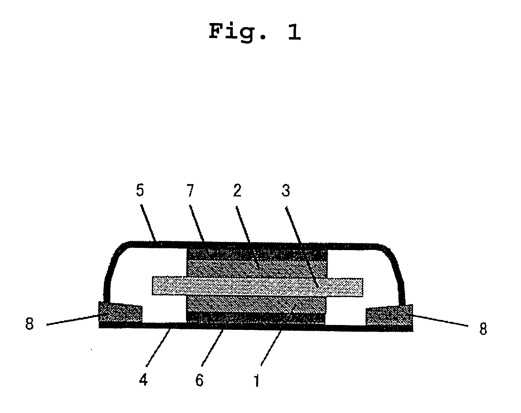
[0043] Silicon powder (purity 99.9%, active material a1) having a mean diameter of primary particles of 270 nm (0.27 .mu.m) as an active material was put in a mortar, and the agglomerated structure of the secondary particles was broken apart into primary particles by a pestle.
[0044] 81.8 weight parts of the silicon powder (active material a1) was added to 8.6 weight % of N-methyl-2-pyrrolidone solution containing 18.2 weight parts of polyimide as a binder and the components were mixed and kneaded by a pestle in a mortar to prepare a slurry.
[0045] The slurry was coated on one surface of an electrolytic copper foil (thickness: 35 .mu.m) having a surface roughness (Ra) of 0.5 .mu.m which is a current collector, and was rolled after drying. A disc having a diameter of 20 mm was cut out from the coated copper foil, and was sintered by heating at 400.degree. C. for 30 hours under an argon atmosphere to prepare a negative electrode. The thickness of the ele...
experiment 2
[0054] Battery A2 was prepared in the same manner as Experiment 1 except that silicon powder (active material a2) having a mean particle diameter of primary particles of 0.8 .mu.m was used in place of the active material a1.
[0055] Battery B1 was prepared in the same manner as Experiment 1 except that silicon powder (active material b1) having a mean particle diameter of primary particles of 1.5 .mu.m was used in place of the active material a1.
[0056] Battery B2 was prepared in the same manner as Experiment 1 except that the active material was mixed in the binder solution by an agitator instead of breaking apart the active material and mixing the slurry in the mortar.
Observation of Active Material Particles in Active Material Layer
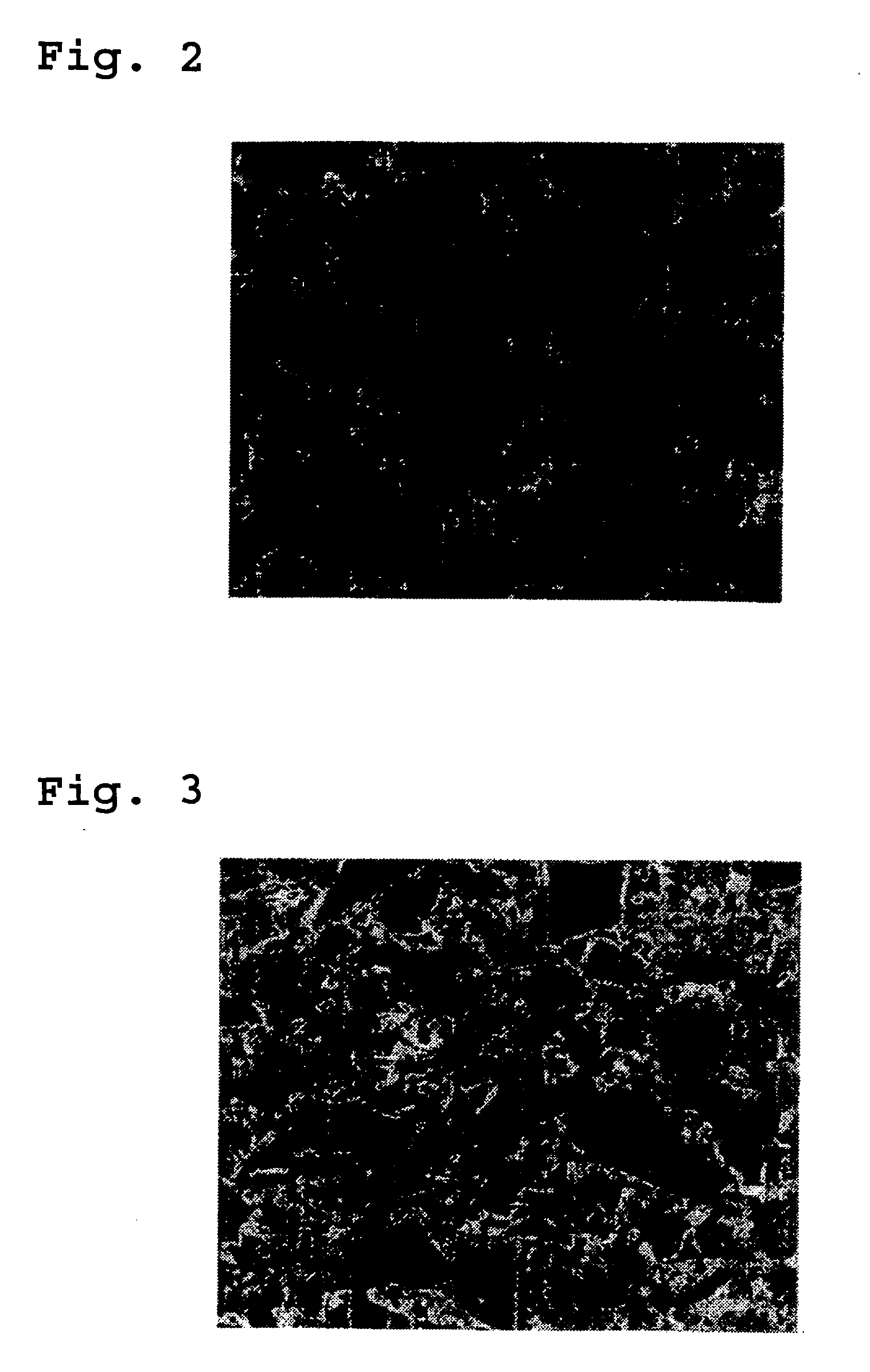
[0057] Sections of the active material layers of the negative electrodes of batteries A1 and B2 were observed by a scanning ion microscope (SIM). FIG. 2 is a section of the active material layer of the negative electrode of battery A1. FIG. 3. is a section...
experiment 3
[0064] The effect of surface roughness (Ra) of the current collector was evaluated.
[0065] Batteries A3 and A4 were prepared in the same manner as Experiment 1 except that an electrolytic copper foil having a surface roughness (Ra) of 0.2 .mu.m and 0.17 .mu.m, respectively, was used instead of the electrolytic copper foil having a surface roughness (Ra) of 0.5 .mu.m.
[0066] Cycle characteristics of batteries A3 and A4 were evaluated in the same manner described above. Cycle life is described as an index when the cycle life of battery A1 is taken as 100. Table 2 also includes the cycle life of battery A1.
3 TABLE 2 Roughness of Surface of Current Collector Battery (.mu.m) Cycle Life A1 0.5 100 A3 0.2 78 A4 0.17 66
[0067] As is clear from the results shown in Table 2, batteries A1 and A3 prepared using a current collector having a surface roughness (Ra) of at least 0.2 .mu.m have excellent cycle characteristics as compared to battery A4 prepared using a current collector having a surface ...
PUM
| Property | Measurement | Unit |
|---|---|---|
| mean diameter | aaaaa | aaaaa |
| Ra | aaaaa | aaaaa |
| diameter | aaaaa | aaaaa |
Abstract
Description
Claims
Application Information
 - R&D
- Intellectual Property
- Life Sciences
- Materials
- Tech Scout
- Unparalleled Data Quality
- Higher Quality Content
- 60% Fewer Hallucinations
Browse by: Latest US Patents, China's latest patents, Technical Efficacy Thesaurus, Application Domain, Technology Topic, Popular Technical Reports.
© 2025 PatSnap. All rights reserved.Legal|Privacy policy|Modern Slavery Act Transparency Statement|Sitemap|About US| Contact US: help@patsnap.com


