

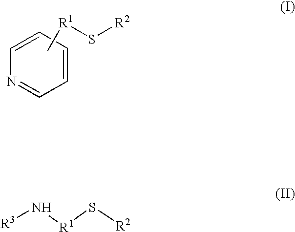
Process for the synthesis of bisphenol
a technology of acidic ion exchange resin and bisphenol, which is applied in the direction of organic compounds/hydrides/coordination complex catalysts, physical/chemical process catalysts, organic chemistry, etc., can solve the problem of significant technical difficulty in applying attached promoters to large commercial scale reactions, and achieve high catalyst selectivity, simplify downstream separation operations, and maximize raw material yield
- Summary
- Abstract
- Description
- Claims
- Application Information
AI Technical Summary
Benefits of technology
Problems solved by technology
Method used
Image


Examples
examples 1-84
Single Column
[0075] 10-15 grams of the modified ion exchange resin catalyst was packed into a column and held in place by a combination of glass wool and sand. The column was surrounded by a water jacket maintained at a temperature of about 55-75.degree. C. as indicated in Table 3. A feed mixture comprising phenol and about 4.8 weight percent acetone, as shown in Table 3, was added to the top of the column. Addition of the feed was controlled by a pump so as to maintain the weight hour space velocity indicated in Table 3. The effluent from the column was collected and analyzed by acetone titration, water titration and liquid chromatography. As can be seen by the results in Table 3 the small scale reactions show a trend of increasing selectivity with increased attachment level. Selectivity however, generally decreases with an increase in the scale of the reaction.
3TABLE 3 Overall Degree of Acetone Temp P / P bisphenol Ex. Promotor Resin Neutralization % (.degree. C.) WHSV selectivity p...
examples 22-26
Multiple Stage
[0076] Four column, each containing 10 grams of modified ion exchange catalyst were arranged in series. After the modified ion exchange resin was added to the columns the resin was flushed with phenol until the amount of water in the effluent was determined to be less than 1% by Karl Fisher titration. The columns were surrounded by water jackets maintained at a temperature of about 55.degree. C. A total of 5 weight % acetone was added in four equal parts (four additions of about 1.25 weight %). Addition of the feed to each column was controlled by a pump so as to attain an overall space velocity of 1-2 WHSV. The effluent from the columns was collected and analyzed by acetone titration, water titration and liquid chromatography. Results are shown in Table 4.
4TABLE 4 Overall Degree of Number of Tempbisphenol Example Promoter Resin Neutralization Acetone % Acetone stages (.degree. C.) p / p selectivity p / p:o / p ratio Conversion selectivity 22 Cysteamine Lewatit 16 5 4 55 96....
example 27
[0077] A reactor system containing 141 kilograms of A121 modified with PEM at a degree of neutralization of 37% using the above described method was rinsed with phenol until the water in the effluent was <1.0% as determined by Karl Fischer titration. The temperature of the feed was kept at about 49.degree. C. The temperature of the effluent was about 74.degree. C. The feed comprised phenol and 5.14% acetone. The overall space velocity was 2.2 WHSV. The effluent from the columns was collected and analyzed by acetone titration, water titration and liquid chromatography. Initial conversion was 98%. The p / p:o / p ratio was 46.4. The p / p selectivity was 96.75%, and overall BPA selectivity was 98.84%.
[0078] As can be seen from the foregoing Examples, it is possible to produce bisphenol on a commercial scale using continuous process employing a modified ion exchange catalyst. Surprisingly, high degrees of neutralization of the ion exchange catalyst result in high levels of convers...
PUM
| Property | Measurement | Unit |
|---|---|---|
| Weight | aaaaa | aaaaa |
| Fraction | aaaaa | aaaaa |
| Fraction | aaaaa | aaaaa |
Abstract
Description
Claims
Application Information