
Crosslinking polymer-supported porous film for battery separator and method for producing battery using the same

Inactive Publication Date: 2004-08-12
NITTO DENKO CORP
View PDF4 Cites 25 Cited by
  • Summary
  • Abstract
  • Description
  • Claims
  • Application Information

AI Technical Summary

Benefits of technology

[0021] According to the present invention, the porous film substrate is not particularly limited so long as it has the above-described properties. Considering solvent resistance and redox resistance, a porous film comprising polyolefin resins such as polyethylene and polypropylene is preferably used. Of those, polyethylene resin film is particularly preferably used as the porous film for the reason that the film has a property such that when heated, the resin melts and clogs the pores, thereby giving a so-called shutdown function to the battery. The polyethylene resin used herein includes not only ethylene homopolymer but also copolymers of ethylene with .alpha.-olefins such as propylene, butene and hexene. Further, laminate films of porous films such as polytetrafluoroethylene and polyimide with the polyolefin resin porous film have excellent heat resistance. Therefore, such laminate films are also preferably used as the porous film substrate in the present invention.

Problems solved by technology

Because face pressure for maintaining the electric connection between the separator and the electrodes cannot sufficiently be applied to the face of the electrodes, the distance between the electrodes partially gets longer over time due to the expansion and shrinkage of electrode active substances during the charge or discharge of the battery.
Thus, the internal resistance of the battery increases, involving deterioration of the battery performance.
Additionally, the occurrence of resistance variation inside the battery also disadvantageously deteriorates the battery performance.
In the case of producing a sheet-like battery of a large area, the distance between the electrodes cannot be fixed, so that satisfactory battery performance cannot be obtained due to the resulting resistance variation inside the battery.
Further, because the amount of the electrolyte solution relative to the adhesive resin cannot increase, the internal resistance of the resulting batteries is high, so that satisfactory cycle performance and high-rate discharge performance cannot be obtained, which is disadvantageous.
If the porous film has a thickness less than 3 .mu.m, the film strength is insufficient, and when such a porous film is used as the battery separator, the electrodes may cause internal short circuit.
On the other hand, when the porous film has a thickness exceeding 50 .mu.m, the battery using such a porous film as the separator has too large distance between the electrodes, so that the internal resistance of the battery is excessive.
When the porosity ratio is too low, such a porous film when used as a battery separator causes reduction in ionic conduction paths so that sufficient battery performance cannot be obtained.
On the other hand, when the porosity ratio is too high, the strength of the film when used as a battery separator is insufficient.
This results in unfavorable increase in the internal resistance of the battery.
When the permeability is too high, such a film when used as a battery separator has low ionic conductivity, so that sufficient battery performance cannot be obtained.
When the puncture strength is less than 1N, the substrate breaks when the face pressure is applied to between the electrodes, which may cause internal short circuit.
As a result, the performance of the resulting battery deteriorates.
As a result, the adhesiveness between the electrodes and the separator in the resulting battery deteriorates.
If the weight average molecular weight is smaller than 10,000, a larger amount of the crosslinking polymers is required for the gelation of the electrolyte solution, resulting in deterioration of the performance of the battery obtained.

Method used


Image

  • Crosslinking polymer-supported porous film for battery separator and method for producing battery using the same
  • Crosslinking polymer-supported porous film for battery separator and method for producing battery using the same
  • Crosslinking polymer-supported porous film for battery separator and method for producing battery using the same

Examples


production example 1

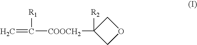
[0076] Production of 3-oxetanyl Group-Containing Crosslinking Polymer A (Weight Average Molecular Weight: 518,000 and Content of 3-oxetanyl Group-Containing Monomer Content: 25% by Weight)

[0077] 60.0 g of methyl methacrylate, 20.0 g of 3-ethyl-3-oxetanylmethyl methacrylate, 158.0 g of ethyl acetate and 0.16 g of N,N'-azobisisobutyronitrile were placed in a 500 ml three-necked flask equipped with a reflux condenser, and mixed for 30 minutes under stirring while introducing nitrogen gas. Radical polymerization was initiated at 60.degree. C. When about 2 hours passed, the viscosity of the reaction mixture began to increase. The reaction mixture was further polymerized for additional 8 hours. The reaction mixture was cooled to about 10.degree. C., and 0.16 g of azobisbutyronitrile was added thereto. The resulting mixture was again heated to 70.degree. C., and polymerization was conducted for 8 hours.

[0078] After completion of the reaction, the reaction mixture was cooled to about 40.deg...

production example 2

[0080] Production of 3-oxetanyl Group-Containing Crosslinking Polymer B (Weight Average Molecular Weight: 253,000 and Content of 3-oxetanyl Group-Containing Monomer Component: 15% by Weight)

[0081] In the same manner as in the Production Example 1, 68.0 g of methyl methacrylate, 12.0 g of 3-ethyl-3-oxetanylmethyl methacrylate, 158.0 g of ethyl acetate and 0.15 g of N,N'-azobisisobutyronitrile were placed in a 500 ml three-necked flask equipped with a reflux condenser, and mixed for 30 minutes under stirring while introducing nitrogen gas. Radical polymerization was initiated at 70.degree. C. When about 1.5 hours passed, the viscosity of the reaction mixture began to increase. The reaction mixture was further polymerized for additional 8 hours. The reaction mixture was cooled to about 40.degree. C., and 0.15 g of azobisbutyronitrile was added thereto. The resulting mixture was again heated to 70.degree. C., and polymerization was conducted for 8 hours.

[0082] After completion of the re...

production example 3

[0084] Production of 3-oxetanyl Group-Containing Crosslinking Polymer C (Weight Average Molecular Weight: 167,000 and Content of 3-oxetanyl Group-Containing Monomer Component: 40% by Weight)

[0085] 48.0 g of methyl methacrylate, 32.0 g of 3-ethyl-3-oxetanylmethyl methacrylate, 58.0 g of ethyl acetate and 0.36 g of N,N'-azobisisobutyronitrile were charged in a 500 ml three-neck flask equipped with a reflux condenser, for mixing were placed in a 500 ml three-necked flask equipped with a reflux condenser, and mixed for 30 minutes under stirring while introducing nitrogen gas, in the same manner as in the Production Example 1. Radical polymerization was initiated at 70.degree. C. When about 1.5 hours passed, the viscosity of the reaction mixture began to increase. The reaction mixture was further polymerized for additional 8 hours. The reaction mixture was cooled to about 40.degree. C., and 0.36 g of azobisbutyronitrile was added thereto. The resulting mixture was again heated to 70.degr...


PUM

PropertyMeasurementUnit
Percent by massaaaaaaaaaa
Porosityaaaaaaaaaa
Weightaaaaaaaaaa

Abstract

A porous film having a crosslinking polymer supported thereon, which can preferably be used for producing a gel electrolyte battery having sufficient adhesion between the electrodes and the separator, low internal resistance and high rate performance, and which can function as a separator in a battery, and a method for producing a gel electrolyte battery using such a crosslinking polymer-supported porous film. The crosslinking polymer-supported porous film for battery separator comprises a porous film substrate having supported thereon a crosslinking polymer having plural cation-polymerizable functional groups in the molecule. The method for producing a battery, includes the steps of: laminating electrodes on the crosslinking polymer-supported porous film to prepare a laminate of crosslinking polymer-supported porous film / electrodes; placing the laminate in a battery container; and pouring an electrolyte solution containing a cation polymerization catalyst in the battery container to induce cation polymerization and crosslinking of the crosslinking polymer, thereby at least partially gelling the electrolyte solution to adhere the porous film and the electrodes.

Description

[0001] The present invention relates to a crosslinking polymer-supported porous film for battery separator, comprising a porous film substrate having supported thereon a crosslinking polymer having plural cation-polymerizable functional groups in the molecule, and a method for producing a battery by adhering electrodes to a separator using the crosslinking polymer-supported porous film.DESCRIPTION OF THE RELATED ART[0002] In recent years, lithium ion secondary batteries with high energy density have been widely used as a power source of small-type hand-held electronic devices such as cell phone and laptop personal computer. Such lithium ion secondary batteries are produced by a process including a step of laminating or winding, for example, a polyolefin resin-porous film on or around positive and negative electrodes in a sheet form to place the resulting laminate in a battery container made of, for example, a metal can, a step of pouring an electrolyte solution in the battery contai...

Claims


Application Information

Patent Timeline
IPC IPC(8): B32B27/30C08J5/18H01M10/05H01M10/0525H01M10/0565H01M10/058H01M50/406H01M50/417H01M50/42H01M50/449H01M50/491
CPCB32B27/30H01M2/145H01M2/1653H01M2/1673H01M2/1686Y10T29/49112H01M10/0565H01M2300/0082H01M2300/0085Y02E60/122H01M10/052Y02P70/50Y02E60/10H01M50/46H01M50/449H01M50/417H01M50/406H01M50/491H01M50/42C08J5/18B32B2323/10B32B2323/04B32B2305/026B32B27/32B32B2379/08B32B27/08B32B2327/18
Inventor UETANI, YOSHIHIROKII, KEISUKENISHIKAWA, SATOSHI
Owner NITTO DENKO CORP
Learn More