Positive electrode of an Electric Double Layer capacitor

a double layer capacitor and positive electrode technology, applied in the direction of capacitor electrodes, electrolytic capacitors, liquid electrolytic capacitors, etc., can solve the problems of prone corrosion or oxidation of the positive electrode of such an edl capacitor, low specific energy, and low discharge and charge currents of edl capacitors employing them, so as to reduce the negative impact of compression on the porosity of the active mass, increase the cycleability of the electrode, and reduce the negative effect of compression

Inactive Publication Date: 2005-01-06
AXION POWER INT
View PDF10 Cites 37 Cited by
  • Summary
  • Abstract
  • Description
  • Claims
  • Application Information

AI Technical Summary

Benefits of technology

[0020] In some embodiments the active mass of the positive electrode can contain one or more dispersed binding agents. In such embodiments it is preferable that the binding agent(s) employed impart higher durability to the active mass so as to diminish the negative impact of compression on the porosity of the active mass and, thereby, increase cycleability of the electrode and an EDL HEC as a whole. The binding agent(s) can be polymers such as PTFE, PVDF, proton-exchange polyfluorsulphonic acid of the Nafion type, glass fiber, etc. Moreover, a dispersed poropho...

Problems solved by technology

A disadvantage of conventional EDL capacitors is that they have rather low specific energies.
A conventional EDL capacitor employing a non-aqueous electrolyte will have a maximum specific energy of about 3 Wh/l and maximum voltage value in the range of 3 to 3.5 V. Non-aqueous electrolytes generally have low conductivity and, as a result, EDL capacitors employing them can only permit relatively low discharge and charge currents.
Employing an aqueous electrolyte produces EDL capacitors having even lower specific energies (e.g., approximately 0.5 to 2 Wh/l) and lower maximum voltage values (e.g., approximately 0.9 V); and furthermore, the positive electrode of such a EDL capacitor is prone to corrosion or oxidation when the EDL capacitor is charged for long periods, as it may be in a backup power supply.
However, because the electrolyte is non-aqueous, this EDL capacitor can only handle/support relatively low discharge and charge currents; and, therefor...

Method used


Image

  • Positive electrode of an Electric Double Layer capacitor
  • Positive electrode of an Electric Double Layer capacitor
  • Positive electrode of an Electric Double Layer capacitor

Examples


example 1

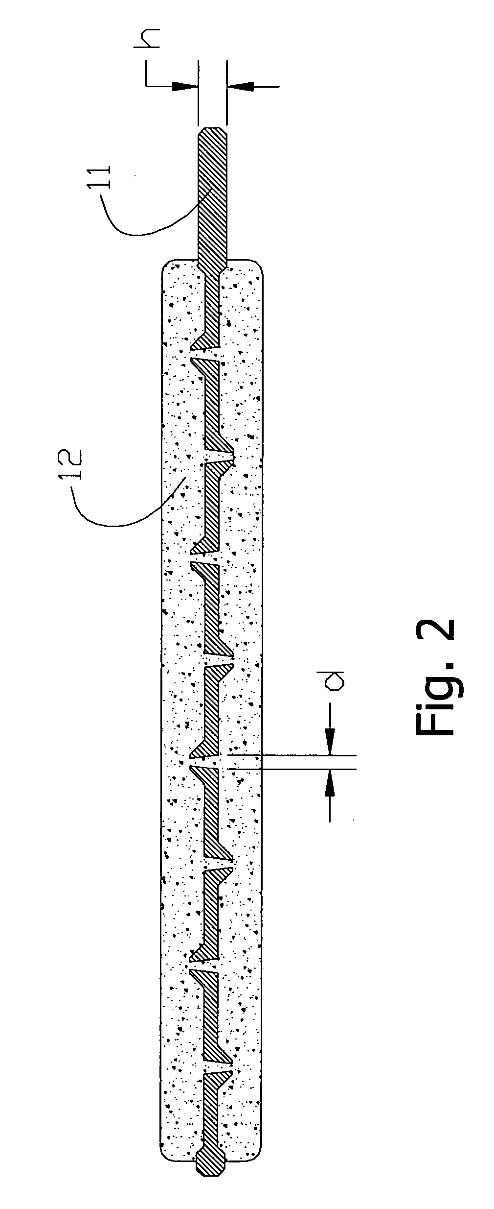
[0049] Referring first to the positive electrode shown in FIG. 2, the lead foil 11 in this example had dimensions of 70×50 mm and a thickness of 0.15 mm. The lead foil 11 was punctured with a punch having 0.6 mm needles. The surface are of the holes was 20% of the total surface area of the lead foil 11. The active mass 12 was prepared from a mixture of pure chemical substances PbO2 and PbSO4 at a 1:0.8 ratio. The initial state of charge of the negative electrode was taken into account when this ratio was determined. A 3% PTFE binding agent in form of water suspension was added to the paste, as well as 3% of finely cut glass fibres. The paste was applied on both sides of the punctured lead foil 11. The pressure applied was 50 kg / cm2. Sintering temperature was 110° C. At a charged state the porosity was 48%, and the specific gravity after excessive charge was 0.3 g / cm2.

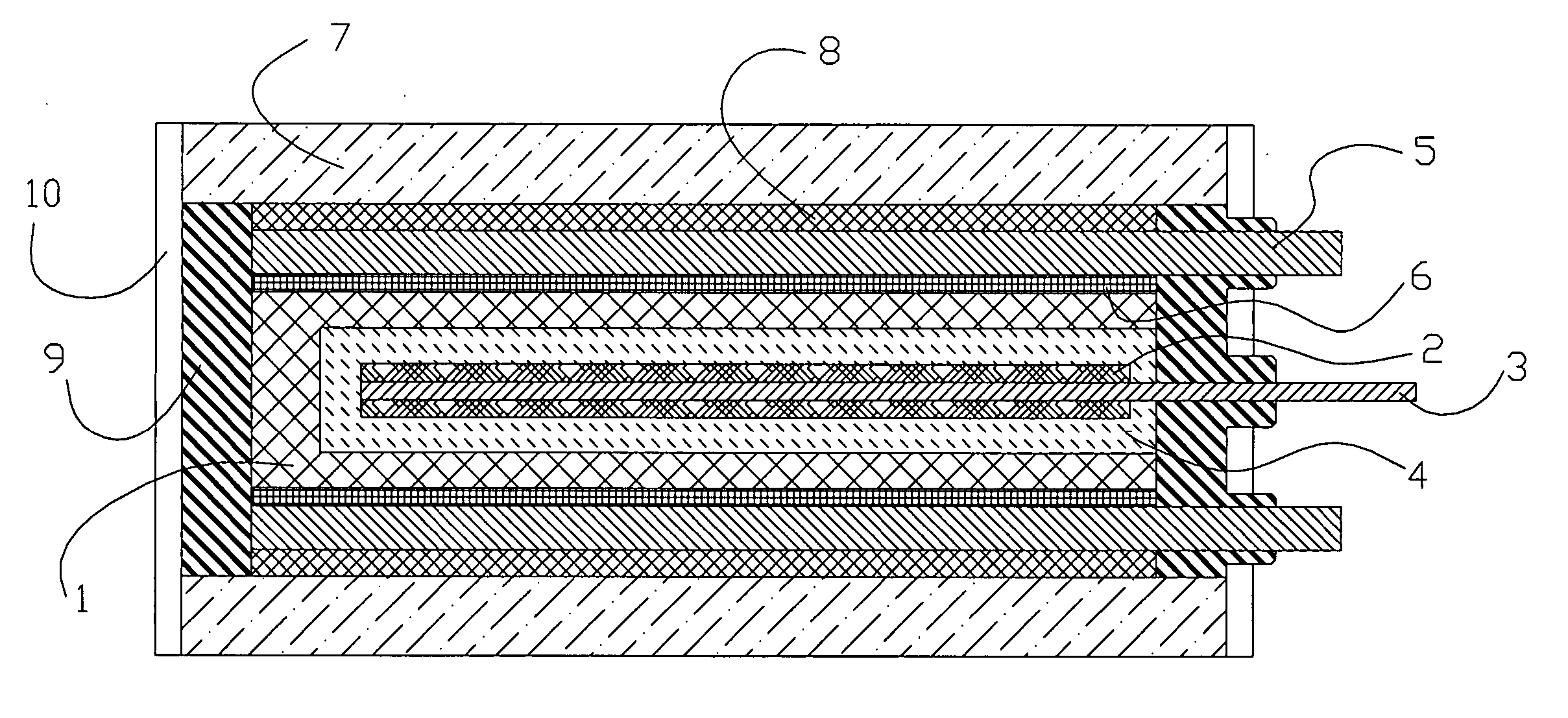
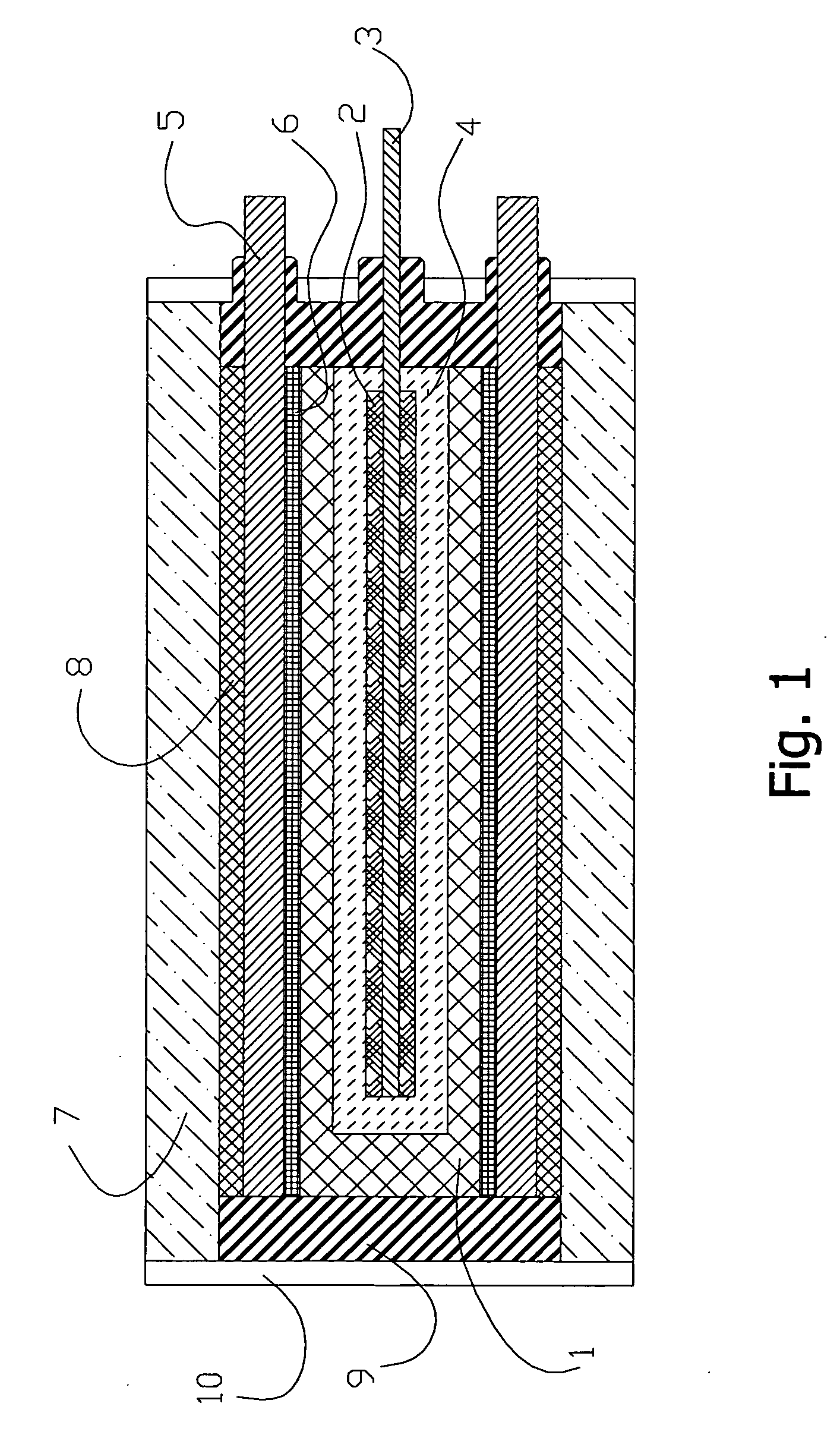
[0050] With further reference to the EDL HEC illustrated in FIG. 1, a negative electrode 1 was made of three layers ...

example 2

[0051] Again referring first to the positive electrode shown in FIG. 2, the lead foil 11 was made of a lead alloy with 0.7% Sn, 0.05% Cu, and 0.01% Ca. The dimensions of the lead foil 11 were 70×50 mm and the thickness 0.4 mm. It was pierced with a punch having 2-mm borers. The surface area of the holes was 30% of the total surface area of the lead foil 11.

[0052] The initial active mass 12 was made from a paste of 4PbO.PbSO4, which is widely used for formation of positive plates in lead-acid batteries. Proton-exchange polyfluorsulphonic acid of Nafion type was added as a binding agent (2%) as well as 3% of finely cut separator of Grace type. The paste was applied on both sides of the punctured lead foil 11 at total amount of 0.5 g / cm2. It was directly formed within the EDL HEC (refer to FIG. 1). The formation was carried out in 10% sulfuric acid to which 0.5% of phosphoric acid was added. The pressure did not exceed 1 kg / cm2. Porosity of the electrodes after formation amounted to 6...

example 3

[0054] Again referring to the positive electrode shown in FIG. 2, the lead foil 11 used in this example had dimensions 70×50 mm and a thickness of 0.1 mm. The lead foil 11 was punctured with a punch having 0.5-mm needles. The surface area of the holes was 15% of the total surface area of the lead foil 11. The active mass 12 was taken from preliminary discharged to 30% positive electrodes of commercially available lead-acid battery. The active mass 12 had particle size of 100 to 200 um. A 4% PVDF binding agent in form of water suspension was added. The paste was applied on one side of the punctured lead foil 11 at total amount of 0.07 g / cm2.

[0055] The electrode was dried at room temperature and pressed with 80 kg / cm2. Sintering temperature was 105° C. At charged state the porosity was 55%. Again, the EDL HEC is depicted in FIG. 1. The negative electrode 1 was made of activated carbon ADG with specific surface of 1150 m2 / g. Layers of the dense rubber gaskets 8 were placed on the back...


PUM


Abstract

Provided in the present invention is a positive electrode for use in an Electric Double Layer (EDL) Hybrid Electrochemical Capacitor (HEC). Embodiments of the invention can be further adapted produce an EDL HEC with a high specific energy value and a high maximum voltage value. Some aspects of an embodiment of the present invention, including the aforementioned positive electrode, also cooperate to provide an EDL HEC that has a relatively high cycleability.

Description

CROSS REFERENCE TO RELATED APPLICATIONS [0001] This application claims the benefit of U.S. Provisional Application No. 60 / 461,440, which was filed on Apr. 9, 2003, and the entire contents of which is hereby incorporated by reference.FIELD OF THE INVENTION [0002] The invention relates to Electric Double Layer (EDL) capacitors, and, in particular to the design of a positive electrode for an EDL capacitor. BACKGROUND OF THE INVENTION [0003] Electric Double Layer (EDL) capacitors have much higher capacitance than conventional electrostatic and electrolytic capacitors—up to tens or hundreds of farads per gram of active electrode material. Consequently, EDL capacitors can be usefully employed as backup power sources in systems requiring uninterrupted electric power supply. For example, EDL capacitors are used for this purpose in computers and communication devices. [0004] For example, some conventional EDL capacitor designs are disclosed in U.S. Pat. Nos. 4,313,084 and 4,562,511. Conventi...

Claims


Application Information

Patent Timeline
IPC IPC(8): H01G9/00H01G9/155
CPCH01G9/155H01G11/72H01G11/58Y02E60/13H01G11/46H01G11/04
Inventor VOLFKOVICH, YURI MIRONOVICHRYCHAGOV, ALEXEY YURIEVICHURISSON, NINA AZRIELEVNASERDYUK, TATIANA M.
Owner AXION POWER INT
Why Eureka
Try Eureka