Devices and methods to image objects

Active Publication Date: 2005-01-06
MENARINI SILICON BIOSYSTEMS SPA
View PDF9 Cites 85 Cited by
  • Summary
  • Abstract
  • Description
  • Claims
  • Application Information

AI Technical Summary

Benefits of technology

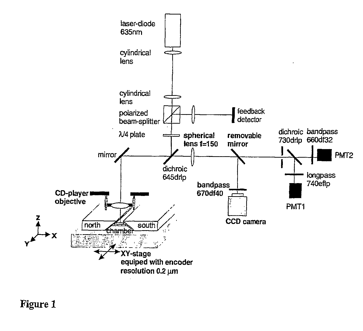
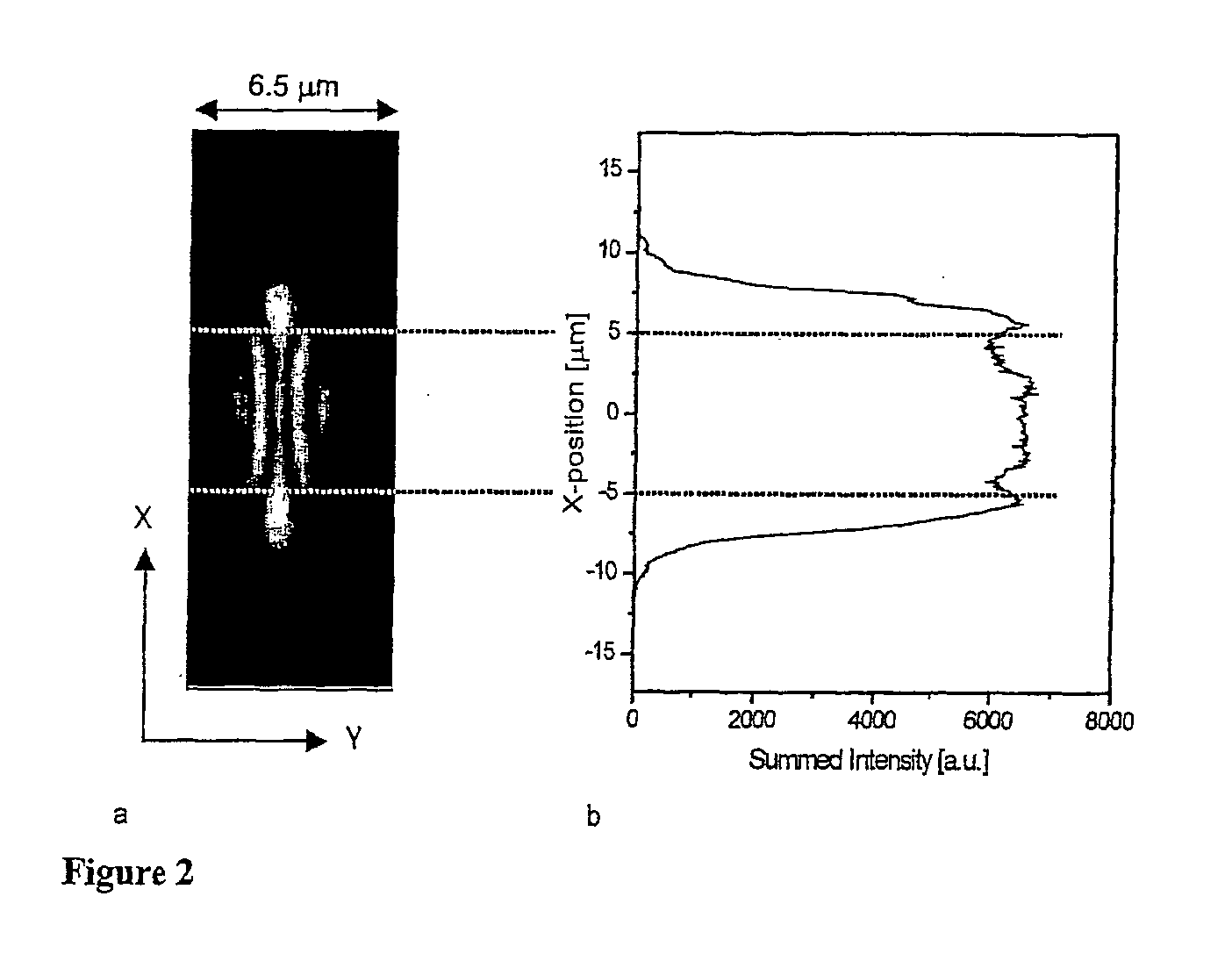
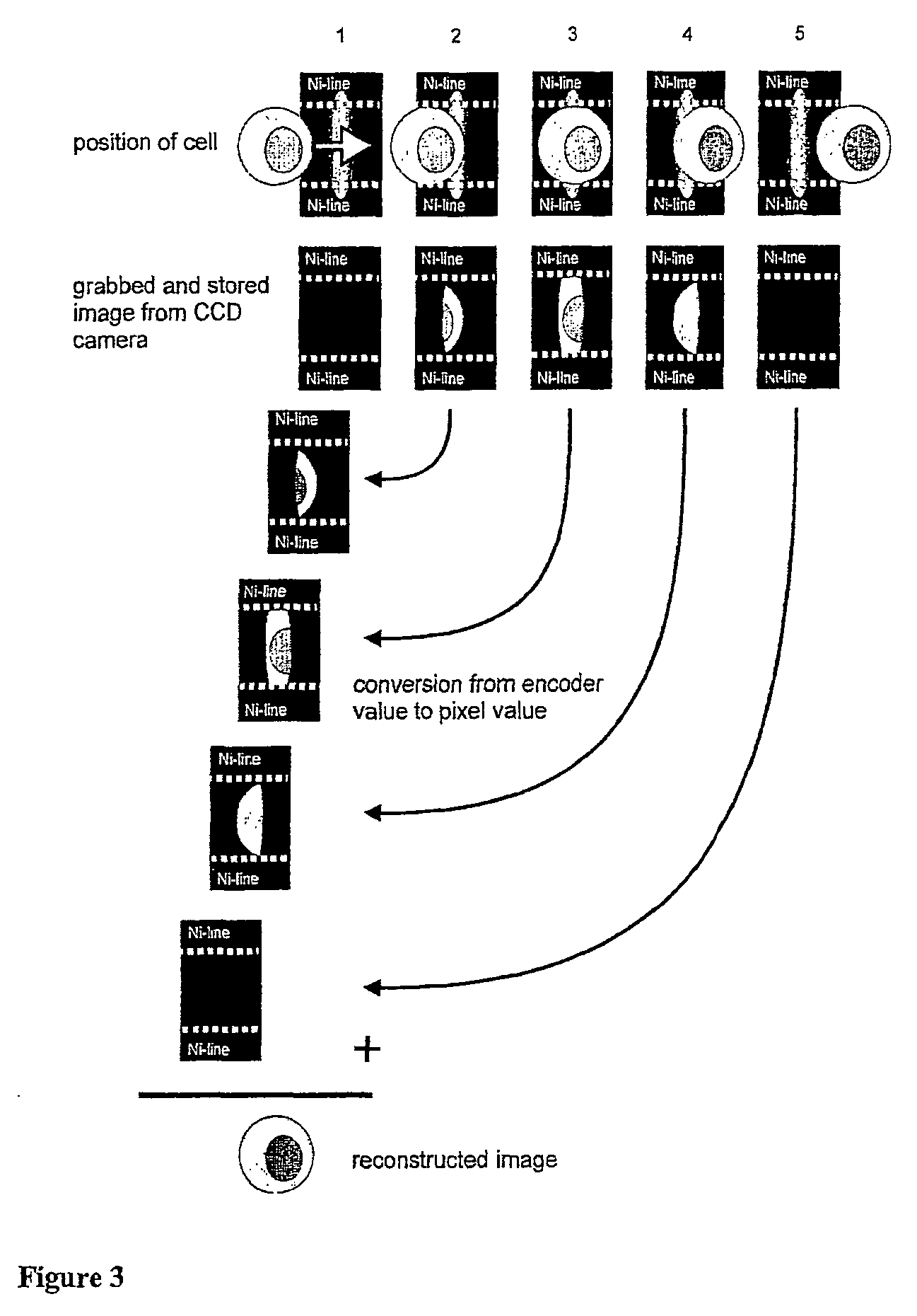
[0006] No liquid flow system is required by the system of the present invention. The magnetic fields induced by the angular magnets in proximity of the nickel lines keep the magnetically labeled cells in fixed positions. This allows revisiting the detected events after measuring the fluorescence emissions and intensities for a more extensive analysis to further identify the detected events. One can microscopically view the images of such events and apply independent morphometric criteria to identify the events as actual cells. Accordingly, in accordance with the present invention, the novel scanning and imaging method provides an improved diagnostic system for detection, classification and enumeration of cells, which comprises an efficient automated means for collecting and aligning imunomagnetically labeled target cells from body fluids, and in which such collected cells also bear at least one immuno-specific fluorescent label that differentiates target from non-target cells labeled with different fluorescent label(s). The images of the collected and aligned cells are reconstructed from indivi

Problems solved by technology

However, morphometric confirmations of the detected events as cells and further molecular evidence is lacking in flow cytometric methods, but is clearly needed to assure that the detected rare events are indeed tumor cells derived from a primary tumor.
Automated image analysis systems have been introduced to reduce subjective errors in cell clas

Method used


Image

  • Devices and methods to image objects
  • Devices and methods to image objects
  • Devices and methods to image objects

Examples


example 1

[0041] For these experiments, 10 μl of fixed SKBR3 cells (50,000 cells / ml) were mixed with 290 μl of EDTA blood. Also added at the same time were 100 μl of magnetic ferrofluid coated with anti-EpCAM (magnetic particles of about 200 nm size coated with proteins, streptavidin and biotinylated EpCAM antibody), an antibody specific for epithelial cells and known to be present on SKBR3 cells (cultured at Immunicon Corp., Huntingdon Valley, Pa.), 10 μl of allophycocyanin (APC) conjugated to monoclonal antibodies recognizing anti-cytokeratin species or cytoskeletal proteins present in epithelial cells (e.g. SKBR3 cells that are epithelium derived) and 10 μl CD45-APC / Cy7 (Caltag, Burlingame, Calif.) to identify leukocytes and identify leukocytes that may nonspecifically bind to cytokeratin antibody. After 15 minutes' incubation, 50 μl of this blood reaction mixture was injected into the chamber. The chamber was placed in the Cell Tracks magnet assembly and after two minutes' collection time...

example 2

[0042] In this experiment 100 μl of EDTA anti-coagulated blood, 50 μl of ferrofluid containing 5 μg of CD45-labeled ferromagnetic nanoparticles, 1.5 μl CD4-APC and 25 μl of 10 −5M Oxazine 750 perchlorate (Exciton Inc., Dayton, Ohio) were added. The optimum concentration of the reagents was obtained by serial titration of each of the reagents. After incubation for 15 minutes, 300 μl PBS was added and 50 μl of the blood mixture was placed into the capillary that was already placed between the magnets. The capillary has a glass bottom shaped in a way that it fits between the 70° tilted faces of the magnets. Two strips of double-sided tape with a thickness of 0.5 mm (3M Co., St. Paul, Minn.) were placed on the glass with spacing of 3 mm to form the sidewalls of the capillary. Ni lines, about 30 μm wide and about 0.21 μm thick, were produced by standard photolithographic techniques on a 7740 Pyrex® glass wafer (Corning International, Germany). Wafers were cut in pieces of 4 mm×25 mm and ...

example 3

[0043] The experiment described in example 2 was repeated but time resolved images were taken with the Cell Tracks system from Oxazine 750 stained and CD45 ferrofluid captured leukocytes in whole blood. FIG. 8 shows four examples of images taken at 20 seconds intervals. The distribution of the fluorescence within the cells is clearly changing between the time intervals and different cells behave differently as is obvious from the cells followed in frame 3 and 4. In both frames images from two cells in close proximity are taken and the differences in uptake and cellular distribution of the Oxazine 750 are apparent. From these examples it is obvious that the Cell Track system has a unique capability to perform functional analysis of cells as, for example, one can study the responses of cells in blood to drugs or other components in real time.


PUM


Abstract

Devices and methods for automated collection and image analysis are disclosed that enable identification or classification of microscopic objects aligned or deposited on surfaces. Such objects, e.g. detectably labeled rare target cells, are magnetically or non-magnetically immobilized and subjected to automated laser scanning to generate sequential digitized x-y sub-images or partial images of target and non-target objects that are combined to form reconstructed full images, thereby allowing detection, enumeration, differentiation and characterization of imaged objects on the basis of size, morphology and immunophenotype.

Description

CROSS REFERENCE TO RELATED APPLICATIONS [0001] This application claims priority under 35 U.S.C. section 119 (e) to U.S. Provisional Application No. 06 / 259,959, filed 5 Jan. 2001, the entire disclosure of which is incorporated by reference herein.TECHNICAL FIELD [0002] This invention relates generally to devices and methods to obtain to scan and obtain images of objects, and more particularly to images reconstructed from partial sub-images of object such as cells obtained from biological fluids that are distributed in a two-dimensional plane. The scanning and imaging technique provided by the invention is especially advantageous for the imaging of cells that are aligned by magnetic means and examined by digitized optoelectronic means. BACKGROUND OF THE INVENTION [0003] The invention of microscopy by Antoni van Leeuwenhoek in 1674 has enabled the visualization of microscopic entities such as cells. The introduction of dyes that stained different components of cells by Paul Ehrlich som...

Claims


Application Information

Patent Timeline
IPC IPC(8): C12M1/34G01N33/543G01N33/574
CPCG01N33/54326
Inventor TIBBE, ARJANGREVE, JANTERSTAPPEN, LEON W.M.M.DE GROOTH, BART
Owner MENARINI SILICON BIOSYSTEMS SPA
Why Eureka
Try Eureka