Apparatus to transfer optical signals between a rotating part and a stationary part of a machine

a technology of optical signals and rotating parts, applied in the field of computer tomographs, can solve the problems of increasing the cost of mechanical precision maintenance and adjustment of individual components of the system, increasing the difficulty of dealing with electromagnetic compatibility problems, and data transmission with such a high transmission rate. achieve the effect of higher signal-to-noise ratio

Inactive Publication Date: 2005-01-20
SIEMENS HEATHCARE GMBH
View PDF15 Cites 14 Cited by
  • Summary
  • Abstract
  • Description
  • Claims
  • Application Information

AI Technical Summary

Benefits of technology

[0017] Starting from this prior art, the object of the present invention is to provide an apparatus for transmitting optical signals be

Problems solved by technology

With known radio-frequency transmission techniques, the data transmission with such a high transmission rate is problematic since the distance between the rotating part and the stationary part is comparable to a quarter of the wavelength.
Shorter wavelengths lead to an increase of the costs for the maintenance of the mechanical precision and the adjustment of the individual components of the system.
Furthermore, it becomes increasingly more difficult to deal with problems of the electromagnetic compatibility.
However, the production precision of such a concentrator is insufficient for many applications with higher transmission rates.
The transmission technique used in these printed publications is additionally only applicable for low data rates, since the adaptation of the electrical delay between the many feed lines that lead to the light sources and/or receivers is difficult.
The greatest difficulty in the realization of this technique exists in the lateral coupling of light into the fiber core with sufficient efficiency.
However, the entrance windows cause a very severe damping of the coupled light upon the propaga

Method used


Image

  • Apparatus to transfer optical signals between a rotating part and a stationary part of a machine
  • Apparatus to transfer optical signals between a rotating part and a stationary part of a machine
  • Apparatus to transfer optical signals between a rotating part and a stationary part of a machine

Examples


Embodiment Construction

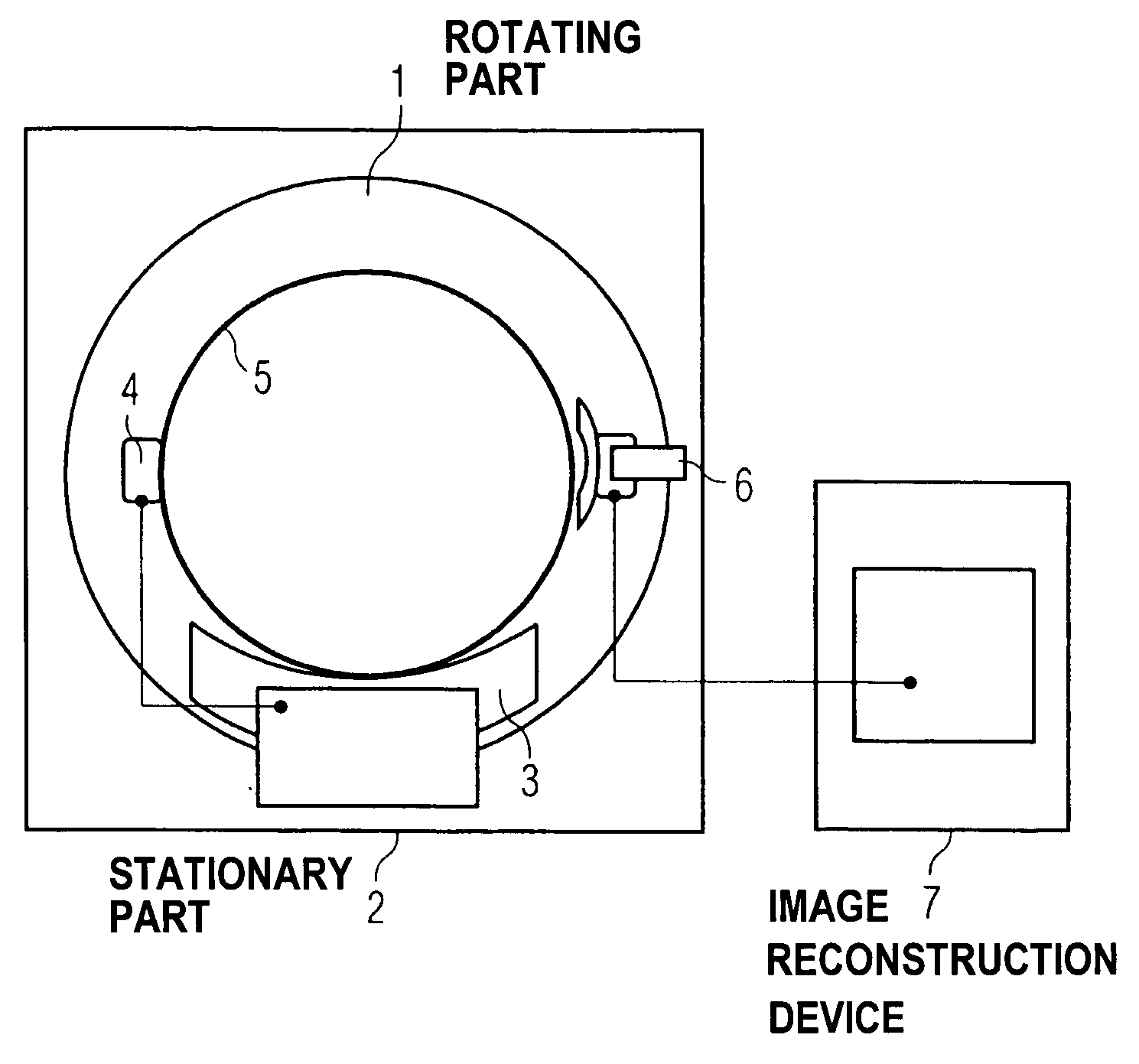
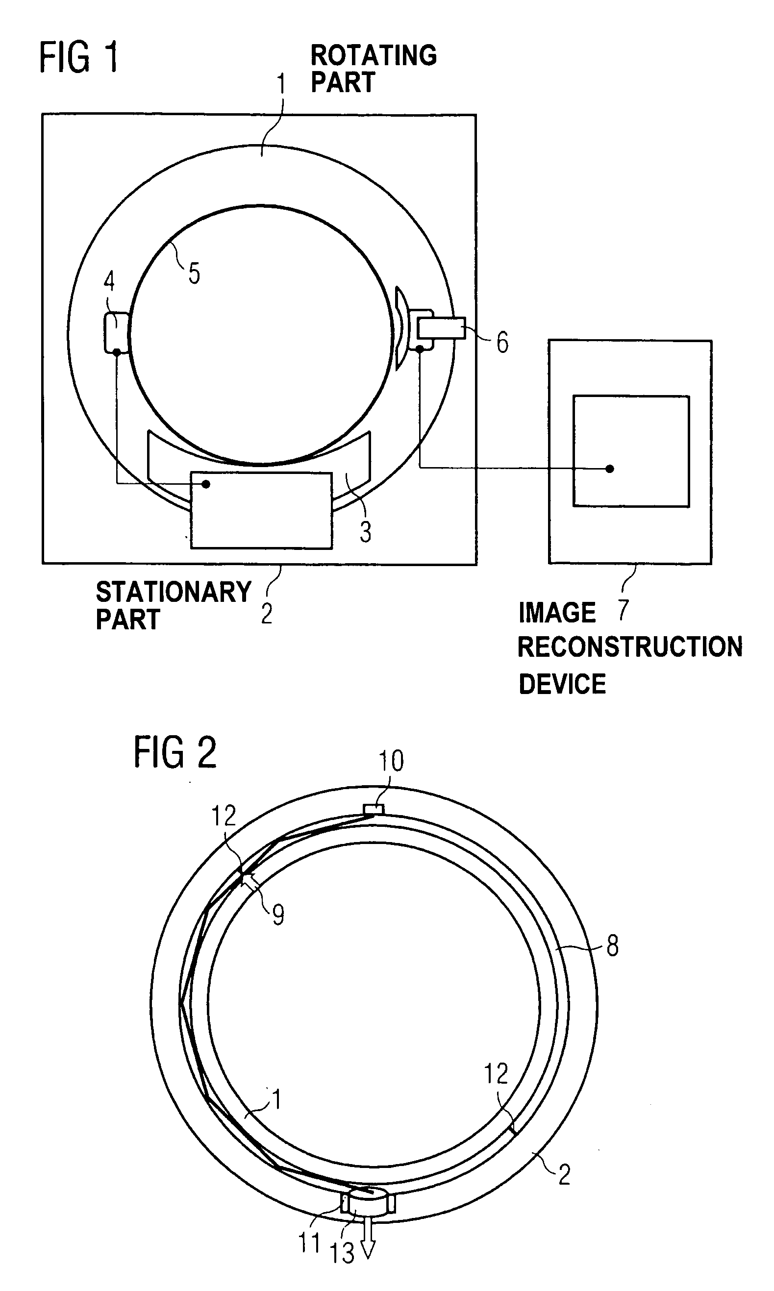
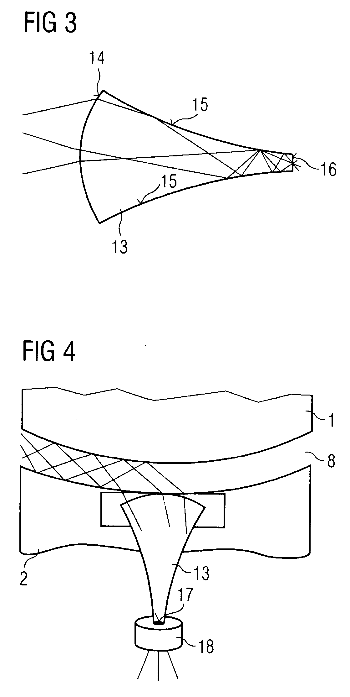
[0035]FIG. 1 shows an embodiment of the transmission path of the measurement data in a computer tomograph that is shown only in a substantially schematic manner without the x-ray source. The measurement data are thereby acquired by the detector bank 3 arranged on the rotating part 1 and transmitted to the transmitter 4 after a parallel-serial conversion. The transmitter 4 comprises a data transmission ring 5 in which the signals propagate. On the stationary part 2, a receiver 6 is arranged that, during the rotation, receives signals decoupled from the ring 5 and forwards them to an image reconstruction device 7 in which the data are extracted from the transmitted signals and undergo a serial-parallel conversion before the further processing. The reception part of the receiver 6 is hereby arranged in direct proximity to the data transmission ring 5 in order to increase the efficiency of the data transmission between both of the elements during the rotation.

[0036] While previously co...


PUM


Abstract

The present invention concerns an apparatus for transmission of optical signals between a rotating part and a stationary part of a machine, particularly a computer tomograph, in which an optical transmitter is arranged on a first of the two parts and an optical receiver with an optical detector is arranged on a second of the two parts, via which optical signals emitted by the optical transmitter are received, whereby the optical receiver comprises an optical concentrator with an at least approximately horn-shaped geometry that concentrates incident optical radiation via internal reflection on side surfaces of the concentrator onto a detection area of the detector. The optical concentrator is formed from a material filling the entire inner volume of the concentrator and optically transparent for at least one wavelength with which the transmitter transmits. A signal-to-noise ratio improved relative to that of known apparatuses for data transmission can be achieved with the present apparatus.

Description

BACKGROUND OF THE INVENTION [0001] The present invention concerns an apparatus to transfer optical signals between a rotating part and a stationary part of a machine, particularly a computer tomograph in which an optical transmitter is arranged on a first of the two parts and an optical receiver with an optical detector is arranged on a second of the two parts, via which optical signals emitted by the optical transmitter are received. The optical receiver comprises an optical concentrator with an at least approximately horn-shaped geometry that concentrates incident optical radiation via internal reflection on side surfaces of the concentrator onto a detection area of the detector. [0002] In many fields of technology today large data quantities are transferred between elements moving relative to on another at a slight distance, particularly individual apparatus parts of a measurement apparatus. The data are thereby frequently acquired with an adjustable apparatus part and, for furth...

Claims


Application Information

Patent Timeline
IPC IPC(8): H04B10/11A61B6/00G02B6/02G02B6/36G02B6/42H04B10/118H04B10/80
CPCA61B6/56G02B6/4214G02B6/4202G02B6/3604
Inventor POPESCU, STEFAN
Owner SIEMENS HEATHCARE GMBH
Why Eureka
Try Eureka