Resist composition

a composition and resist technology, applied in the field of resist compositions, can solve the problems of reducing the wavelength of light sources, reducing the depth of focus range, altering the refractive index of solvents, etc., and achieves the effects of low sensitivity, low cost and low swelling

Active Publication Date: 2005-01-20
TOKYO OHKA KOGYO CO LTD
View PDF29 Cites 86 Cited by
  • Summary
  • Abstract
  • Description
  • Claims
  • Application Information

AI Technical Summary

Benefits of technology

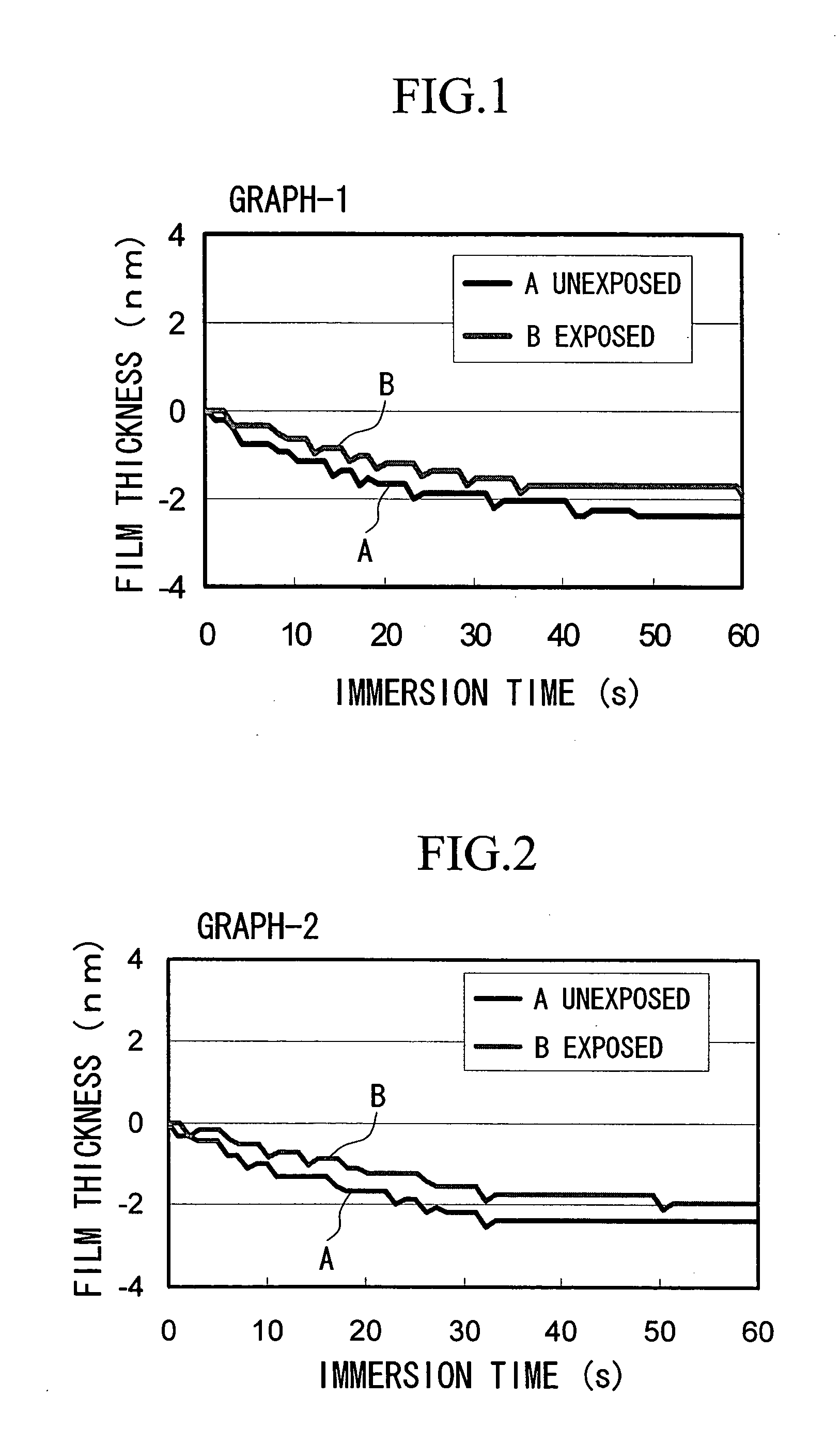
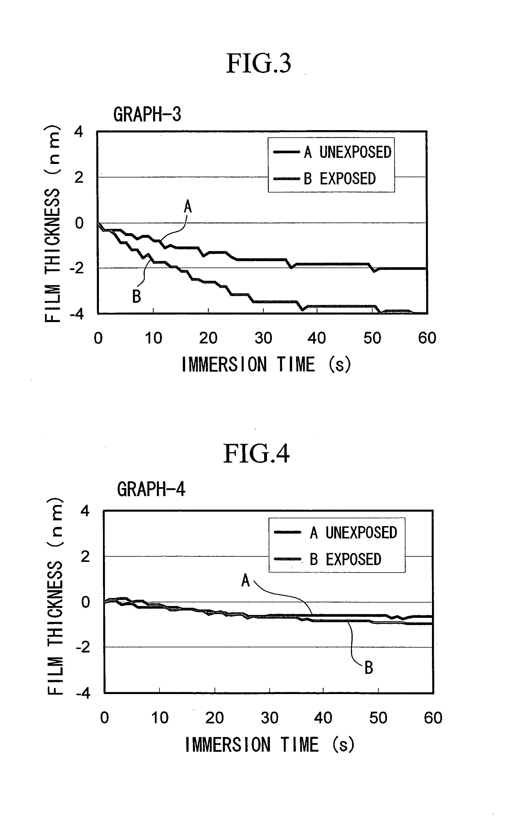
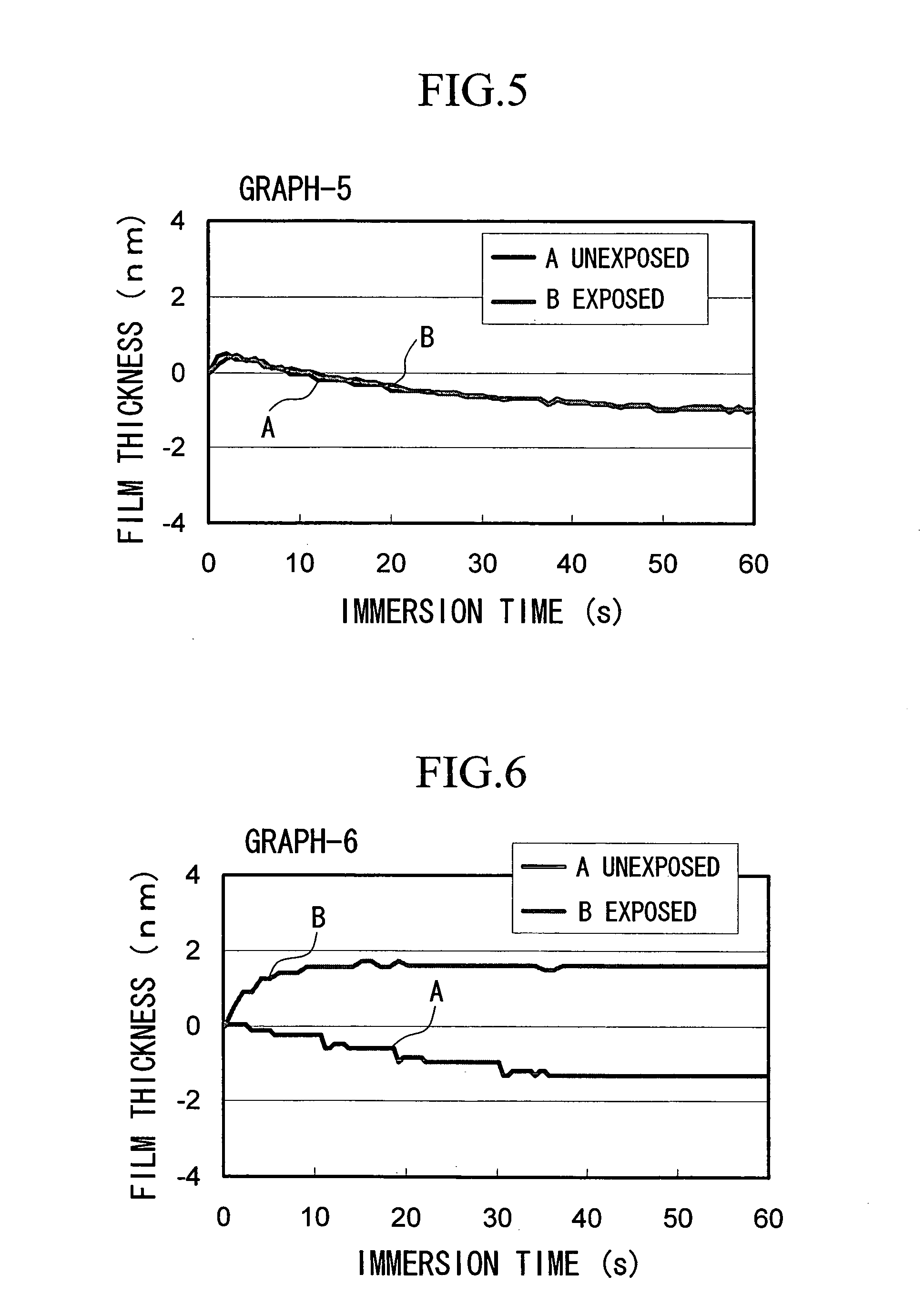
According to the present invention, a high precision resist pattern which displays no surface roughening of the resist pattern such as the formation of T-top shaped patterns, and displays minimal deterioration in sensitivity, little swelling, and an excellent resist pattern profile can be produced using immersion lithography. Accordingly, by using a resist composition of the present invention, resist pattern formation that comprises an immersion lithography step can be carried out effectively.

Problems solved by technology

However, reducing the wavelength of the light source requires a new and expensive exposure apparatus, and if the NA value is increased, then because the resolution and the depth of focus range exist in a trade-off type relationship, even if the resolution is increased, the depth of focus range reduces.
However, because the resist layer comes in contact with a solvent during exposure as described above, a variety of problems can arise, such as degeneration of the resist layer, or the leaching of components from the resist that have a deleterious effect on the solvent, thus altering the refractive index of the solvent and impairing the inherent advantages offered by the immersion lithography process.
Accordingly, it remains unclear whether or not immersion lithography is capable of forming a resist pattern of equivalent quality to those produced by conventional exposure processes.
When an attempt was made to apply conventional KrF resists and ArF resist compositions to immersion lithography, a variety of problems emerged due to the effects of the solvent, including deterioration in the sensitivity, roughening of the surface of the resist pattern (a deterioration in the profile shape) such as the formation of T-top shaped resist patterns, or swelling of the resist pattern.

Method used


Image

  • Resist composition
  • Resist composition
  • Resist composition

Examples


example 1

A component (A), a component (B) and a component (D) described below were dissolved uniformly in a component (C), yielding a positive resist composition 1.

As the component (A), 100 parts by weight of a methacrylate-acrylate copolymer comprising the three structural units shown in the [formula 21] was used. The proportions p, q and r of each of the structural units used in preparing the component (A) were p=50 mol %, q=30 mol % and r=20 mol % respectively. This copolymer contained no structural units containing an anhydride of a dicarboxylic acid, and no structural units containing a phenolic hydroxyl group. The weight average molecular weight of the thus prepared component (A) was 10,000.

As the component (B), 3.5 parts by weight of triphenylsulfonium nonafluorobutanesulfonate and 1.0 parts by weight of (4-methylphenyl)diphenylsulfonium trifluoromethanesulfonate were used.

As the component (C), 1900 parts by weight of a mixed solvent of propylene glycol monomethyl ether acetat...

example 2

A component (A), a component (B), a component (D) and the other component described below were dissolved uniformly in a component (C), yielding a positive resist composition 2.

As the component (A), 100 parts by weight of a methacrylate copolymer comprising the three structural units shown in the [formula 22] was used. The proportions p, q and r of each of the structural units used in preparing the component (A) were p=40 mol %, q=40 mol % and r=20 mol % respectively. This copolymer contained no structural units containing an anhydride of a dicarboxylic acid, and no structural units containing a phenolic hydroxyl group. The weight average molecular weight of the thus prepared component (A) was 10,000.

As the component (B), 2.0 parts by weight of (4-methylphenyl)diphenylsulfonium nonafluorobutanesulfonate and 0.8 parts by weight of tri(p-tert-butylphenyl)sulfonium trifluoromethanesulfonate were used.

As the component (C), 700 parts by weight of a mixed solvent of propylene glyco...

example 4

A resin component comprising a repeating unit represented by a chemical formula shown below

(wherein, m:n is 84:16 (mol %)), 10% by weight, relative to this resin component, of a water insoluble cross linking agent formed from tetrabutoxymethylated glycoluril, 1% by weight of an acid generator formed from triphenylsulfonium nonafluorobutanesulfonate, and 0.6% by weight of an amine component formed from 4-phenylpyridine were dissolved in propylene glycol monomethyl ether, yielding a negative resist composition with a solid fraction component of 8.1% by weight.

Meanwhile, an organic anti-reflective film composition AR-19 (manufactured by Shipley Co., Ltd.) was applied to the surface of a silicon wafer using a spinner, and was then baked and dried at 215° C. for 60 seconds on a hotplate, thereby forming an anti-reflective film layer with a film thickness of 82 nm. The negative resist composition obtained above was applied on top of the anti-reflective film using a spinner, and was ...


PUM

PropertyMeasurementUnit
thicknessaaaaaaaaaa
widthaaaaaaaaaa
thicknessaaaaaaaaaa

Abstract

A resist composition which is stable relative to solvents used in immersion lithography processes and displays excellent sensitivity and resist pattern profile, and a method of forming a resist pattern that uses such a resist composition are provided. The resist composition is in accordance with predetermined parameters, or is a positive resist composition comprising a resin component (A) which contains an acid dissociable, dissolution inhibiting group and displays increased alkali solubility under the action of acid, an acid generator component (B), and an organic solvent (C), wherein the component (A) contains a structural unit (a1) derived from a (meth)acrylate ester containing an acid dissociable, dissolution inhibiting group, but contains no structural units (a0), including structural units (a0-1) containing an anhydride of a dicarboxylic acid and structural units (a0-2) containing a phenolic hydroxyl group.

Description

CROSS-REFERENCE TO RELATED APPLICATION This application is a continuation-in-part application of International Application No. PCT / JP2004 / 000704, filed Jan. 27, 2004, which claims priorities of Japanese patent application Nos. 2003-025152 filed Jan. 31, 2003, 2003-045000 filed Feb. 21, 2003, 2003-062531 filed Mar. 7, 2003, 2003-125244 filed Apr. 30, 2003, 2003-157257 filed Jun. 2, 2003, 2003-195403 filed Jul. 10, 2003, 2003-426939 filed Dec. 24, 2003 and 2004-017355 filed Jan. 26, 2003, the contents of all of which are incorporated herein by reference. BACKGROUND OF THE INVENTION 1. Field of the Invention The present invention relates to a positive or negative resist composition used in a resist pattern formation method that comprises an immersion lithography (immersion exposure) step, and a method of forming a resist pattern that uses such a resist composition. 2. Description of Related Art Lithography techniques are widely used in the production of microscopic structures in a...

Claims


Application Information

Patent Timeline
Patent Type & Authority Applications(United States)
IPC IPC(8): G03C1/76G03F7/004G03F7/038G03F7/039G03F7/20G03F7/26H01L21/027
CPCG03F7/0382G03F7/0397G03F7/2041Y10S430/111G03F7/70616Y10S430/106G03F7/70341G03F7/039G03F7/26
Inventor HIRAYAMA, TAKUHADA, HIDEOFUJIMURA, SATOSHIIWAI, TAKESHISATO, MITSURUTAKASU, RYOICHITACHIKAWA, TOSHIKAZUIWASHITA, JUNISHIDUKA, KEITAYAMADA, TOMOTAKATAKAYAMA, TOSHIKAZUYOSHIDA, MASAAKI
Owner TOKYO OHKA KOGYO CO LTD
Why Eureka
Try Eureka