3-D adaptive laser powder fusion welding

a laser technology, applied in the field of laser powder fusion welding systems, can solve the problems of increased cost, increased operation costs, and high probability of defect rates or the inability to use lpfw at all, and achieve the effect of easy and quick achievemen

Inactive Publication Date: 2005-02-03
HONEYWELL INT INC
View PDF51 Cites 36 Cited by
  • Summary
  • Abstract
  • Description
  • Claims
  • Application Information

AI Technical Summary

Benefits of technology

[0015] By providing such a system, manufacture, alteration, and repair of parts that are subject to laser powder fusion welding are readily and easily achieved. Furthermore, those materials which are generally not subject to regular welding processes are now opened up for commercial and technical exploitation due to the removal of the prior obstacle of not being susceptible to normal welding processes.
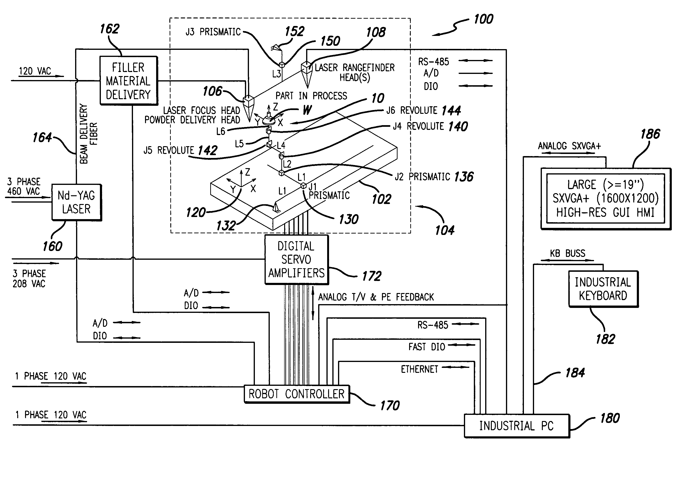
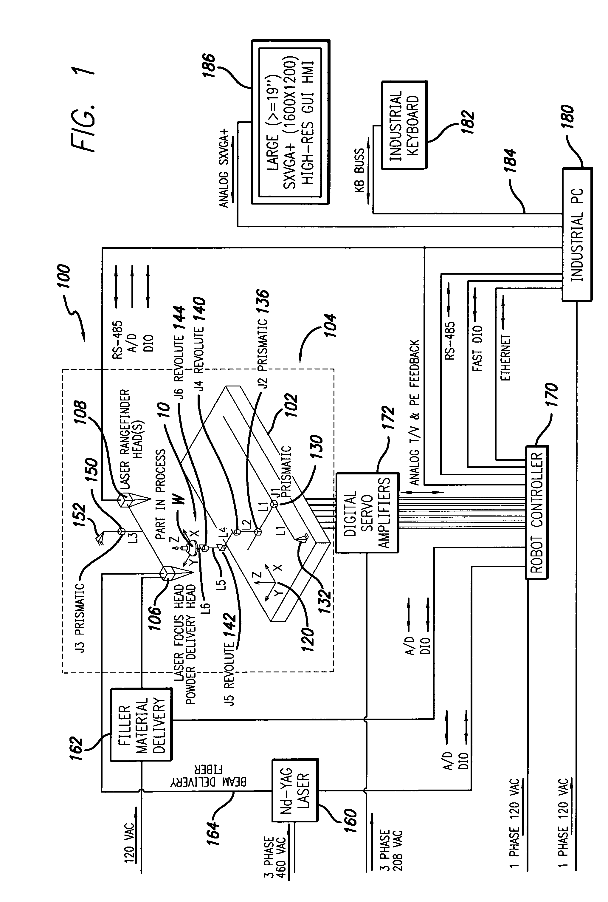
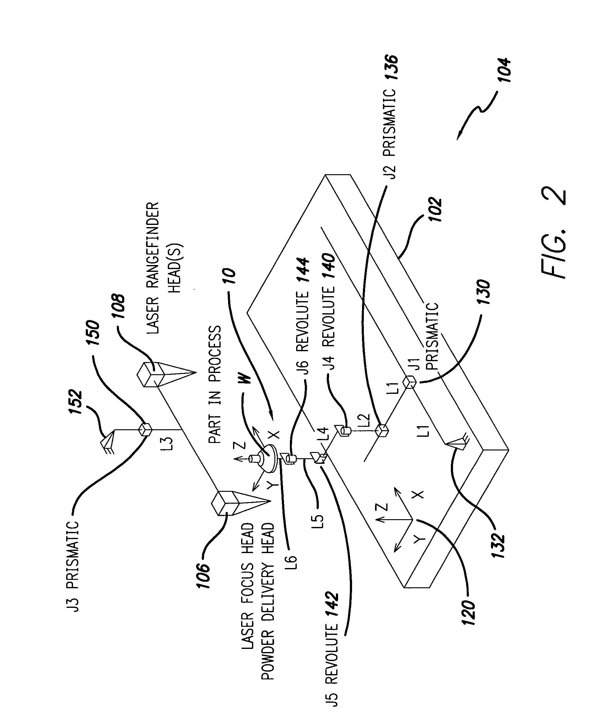
[0016] In one embodiment, the 3-D adaptive laser powder fusion welding system subjects a workpiece to laser powder fusion welding via a laser head system and a linear displacement element coupled to the laser head and enabling the laser head to be displaced linearly in a first dimension. A support apparatus holds the workpiece adjacent the laser head in an adjustable and selectable manner and provides five degrees of freedom for the workpiece in second and third linear dimensions and first, second, and third rotational dimensions. In this way; the laser head may engage the workpiece about its exterior. By so engaging the workpiece, the welding system enables welding to occur at almost any, if not every, surface of the workpiece.
[0017] In another embodiment, the 3-D adaptive laser powder fusion welding system subjects a workpiece to laser powder fusion welding via a laser head system that includes a laser welding head, a powder feed delivery system, and a tracing system that determines the topology of the workpiece. A linear displacement element coupled to the laser head enables the laser head to be displaced linearly in a first dimension and a support apparatus holds the workpiece adjacent the laser head in an adjustable and selectable manner. The support apparatus provides five additional degrees of freedom for the workpiece in second and third linear dimensions and first, second, and third rotational dimensions. The support apparatus including an x-axis prismatic element enabling linear travel along a first linear axis, a y-axis prismatic element enabling linear travel along a second linear axis, a roll revolute element enabling angular travel centered upon a roll axis, a pitch revolute element enabling angular travel centered upon a pitch axis, a yaw revolute element enabling angular travel centered upon a yaw axis. The x-axis, y-axis, roll revolute element, pitch revolute element, and yaw revolute elements are coupled to one another. A filler delivery system providing filler material to the laser head system. A laser supplying laser light to the laser head system is included and may generally rely upon an Nd-YAG laser. Alternative sources of laser energy may also be used, including lasers based on or using carbon dioxide (CO2) and / or yttrium fiber diode laser systems. A controller system controls operation of the filler delivery system, the laser, the laser head system, the linear displacement element, and the support apparatus. The controller system includes: a digital servo amplifier system coupled to the support apparatus and controlling operation of the five degrees of freedom; a robot controller coupled to and controlling the laser head system, the linear displacement element, and the digital servo amplifier; and a computer programmably operating the robot controller and enabling recording of data through the controller system. The 3-D LPF system is able to engage the workpiece about an exterior of the workpiece and by so engaging the workpiece, the welding system enables welding to occur at almost any, if not every, surface of the workpiece.

Problems solved by technology

Current means do not allow for significant workpiece manipulation for engagement by the LPFW head or significant LPFW head manipulation for workpiece engagement.
This causes or may lead to a higher probability of defect rates or the inability to use LPFW at all unless the components are machined prior to welding in a manner that minimizes such variation.
Such additional operations increase cost due to the added labor and material.
They also increase the time it takes to operate on the workpiece.
Currently, there are no machines or processes available to adapt to multi-dimensional part variability.
Existing laser welding systems do not have the capability to trace and program a complex geometry for a part in a manner that positions the laser normal to the surface in a constant fixed distance during LPF (Laser Powder Fusion) welding.

Method used


Image

  • 3-D adaptive laser powder fusion welding
  • 3-D adaptive laser powder fusion welding
  • 3-D adaptive laser powder fusion welding

Examples


Embodiment Construction

)

[0021] The detailed description set forth below in connection with the appended drawings is intended as a description of presently-preferred embodiments of the invention and does not represent the only forms in which the present invention may be constructed and / or utilized. The description sets forth the functions and the sequence of steps for constructing and operating the invention in connection with the illustrated embodiments. However, it is to be understood that the same or equivalent functions and sequences may be accomplished by different embodiments that are also intended to be encompassed within the spirit and scope of the invention.

[0022] The 3-D adaptive laser powder fusion welding system 100 has a central table or platform 102 upon which geometrical control elements (generally indicated as 104) operate in order to dispose a workpiece W in relation to either a laser powder fusion welding head 106 or a laser rangefinder head 108. The geometrical control elements 104 gene...


PUM

PropertyMeasurementUnit
degrees of freedomaaaaaaaaaa
timeaaaaaaaaaa
temperatureaaaaaaaaaa

Abstract

A 3-D adaptive laser powder fusion welding system provides for both modeling/gauging of a workpiece as well as repair, restoration, and/or manufacture thereof. By providing a work platform and apparatus support system, five degrees of control in the form of two linear axes and three rotational axes are provided. The sixth linear axis is controlled via the displacement of a laser powder fusion (LPF) welding head and a laser rangefinding head. The laser rangefinding head system enables the workpiece W to be modeled electronically or otherwise. Additionally, the rangefinding system enables a model part to serve as a template from which repairs or construction are affected. The LPF welding head then affects any repairs or manufacture that are needed on the workpiece W. The LPF welding head is powered by filler material. The entire system is generally controlled by computer which enable the operator to be separated from a generally hot and hostile welding environment.

Description

CROSS-REFERENCES TO RELATED APPLICATIONS [0001] This patent application is related to, but claims no priority from, U.S. Pat. Ser. No. 10 / 071,025 filed Feb. 8, 2002 for Hand Held Laser Powder Fusion Welding Torch and U.S. Pat. Ser. No. 10 / 206,411 filed Jul. 26, 2002 for Powder Feed Splitter for Hand-Held Laser Powder Fusion Welding Torch, which are incorporated by reference.COPYRIGHT AUTHORIZATION [0002] Portions of the disclosure of this patent document may contain material which is subject to copyright and / or mask work protection. The copyright and / or mask work owner has no objection to the facsimile reproduction by anyone of the patent document or the patent disclosure, as it appears in the Patent and Trademark Office patent file or records, but otherwise reserves all copyright and / or mask work rights whatsoever. BACKGROUND OF THE INVENTION [0003] 1. Field of the Invention [0004] This invention relates to Laser Powder Fusion Welding (LPFW) Systems and more particularly to a platf...

Claims


Application Information

Patent Timeline
Patent Type & Authority Applications(United States)
IPC IPC(8): B23K26/08B23K26/34
CPCB23K26/0823B23K26/34B23K26/3206B23K26/322B23K26/3246B23K26/3266B23K35/0244B23K26/345B22F2003/1058B29C67/0077B23P6/007B23K35/0255B23K2201/36B23K26/328B23K26/342B23K26/0853B23K26/0869B23K26/144Y02P10/25B22F12/222B22F12/226B22F12/224B22F10/25B22F12/41B29C64/153
Inventor SANKARANARAYANAN, SRIKANTHHUSSEY, JAMES M.WINCHESTER, GARY L.HEHMANN, WILLIAM
Owner HONEYWELL INT INC
Why Eureka
Try Eureka