[0024] Systems according to the present invention employ a pressure vessel housing a number of filtration elements, such as RO elements, arranged in a string or series, and are configured to produce permeate streams under two sets of conditions or to produce separate or separable permeate outputs of two (or more) different qualities. In accordance with one aspect of the invention, a vessel and / or the filter cartridges themselves are arranged to split the flow of permeate from the elements into two streams. In accordance with another aspect of the invention, the vessels and filter cartridges may produce a single permeate output, but may also control the pressure and / or the
back pressure acting on separate individual filter elements or subgroups of one or more filter elements within a
single vessel to enhance operation and / or performance.
[0025] A treatment
plant using a
system according to the present invention as
one stage or treatment may treat one or more of the permeate streams from that stage (such as a lesser-quality
stream) by further processes, such as
reverse osmosis,
nanofiltration,
ion exchange,
electrodialysis (either unfilled or filled
cell electrodialysis),
dialysis,
distillation,
ultraviolet light, absorption in or adsorption on various media. The treated stream(s) may be blended back with a higher quality permeate (e.g., from upstream filter elements) to produce a product meeting maximum predetermined or specified concentrations or concentration ranges. Treating only permeate from downstream elements in such further processes results in much lower equipment costs as such costs correspond to the volumetric flow rate of the liquid to be treated.
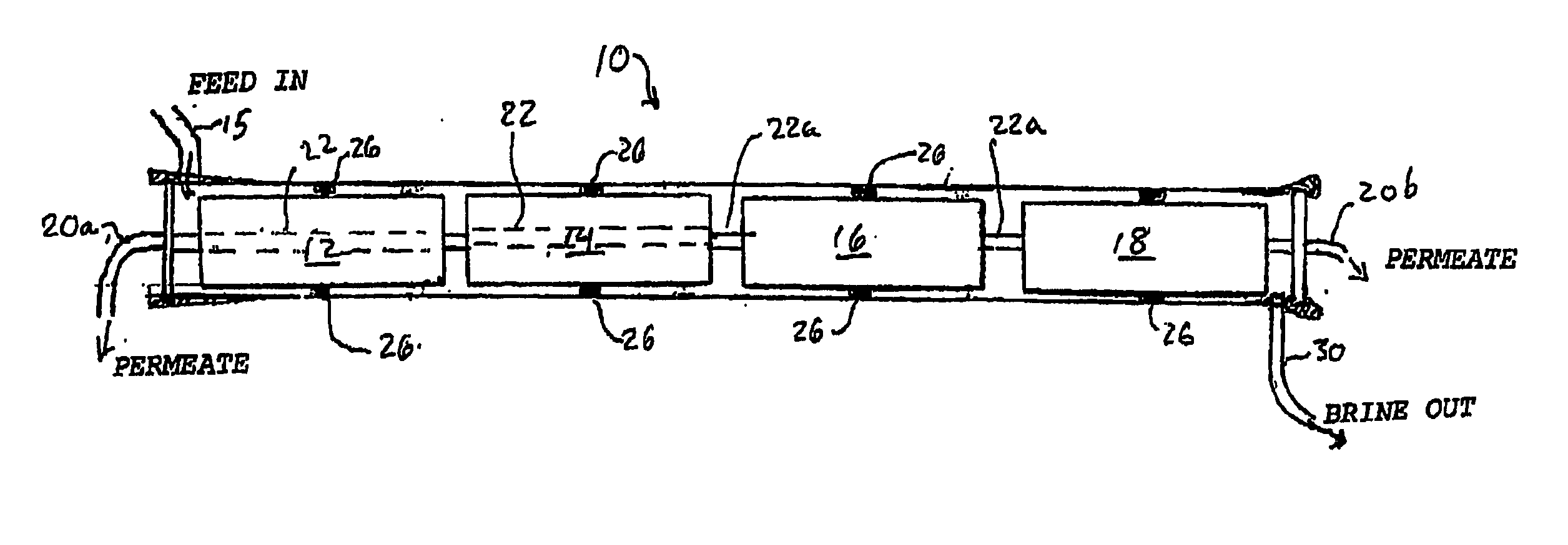
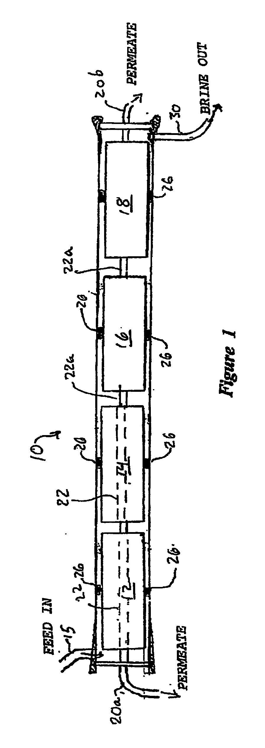
[0026] One or more of the foregoing desirable ends and operating advantages are obtained in accordance with one aspect of the present invention by a cross flow filtration apparatus, such as a reverse
osmosis (RO) apparatus, having an elongated pressure vessel, such as a cylinder, with a side entry port. The vessel has a length to accommodate a plurality of n filter cartridges positioned within the vessel, wherein n is an integer of two or greater, preferably four or greater. The side entry port is preferably placed at an
intermediate stage of the vessel's length so that the feed flow is divided into a first feed flow directed through a first filtration
branch or set of less than all of said filter cartridges, and a second feed flow directed through a second filtration
branch comprised of the remaining ones of said filter cartridges. The first and second branches extend in opposite senses, toward respective ends of the vessel, while permeate or filtrate passes through the membranes and is collected in the permeate manifolds of cartridges in both branches. A spacer-adapter may bifurcate the feed flow and direct it centrally outward into the cartridges of the first and second branches. In a preferred embodiment, the two filtration branches are of equal length, i.e., contain equal numbers of filtration elements. This
system produces a filtrate stream of enhanced permeate
transfer efficiency and quality, with a large number of cartridges arranged along short flow paths and operating with a lower overall pressure drop per stage.
[0028]
Large capacity water purification plants may employ plural banks of such side-entry vessels in series to achieve a high capacity staged system. Each
bank may comprise the same or a different number of vessels, or vessels of a different length comprising different numbers of filtration cartridges. The system may employ a booster or interstage pump ahead of a downstream
bank, as known in the art, to set a flux-optimized pressure that maintains the desired through-flow at a minimal power cost. Systems may be configured with flow valves that may be controlled to direct the permeate from one
bank to back flush or to effect cleaning cycles of another bank so as to maintain operating efficiency of the various banks or modules within the system. Advantageously, systems of the invention may operate with lower pressure drop per stage compared to systems having the same number of cartridges with end-vessel inlets and outlets. In a two-stage or multistage system, this may obviate the need for an interstage booster, and it further enables substitution of less costly equipment, and / or different configurations of equipment, and
recovery of or direct utilization of the first stage output pressure in downstream stages or passes.
[0030] A filter cartridge for use in a system according to the present invention may be a conventional cartridge. It may have a central
pipe forming a manifold communicating with the interior of the RO membrane for collecting the permeate from the cartridge. Typically, each central pipe or flow tube, or other manifold structure, sealingly interfits with or connects to a corresponding tube or structure of an adjacent cartridge, and forms a seal thereagainst in a manner known in the art (e.g., with a short stub-connector). The cartridge may also include a disk-like end cap having a
peripheral seal, e.g., one that seats against the inner wall of the vessel along its outer edge. The seal may include an O-ring seal or packing, or may be a looser or directionally-flexible seal such as a chevron seal. In the latter case, when used with a side entry vessel of the present invention, the vessels are preferably loaded with two sets of filter cartridges having their chevron seals facing in opposite directions in the two branches. This permits both branches to obtain suitable sealing around their periphery to prevent feed stream bypass flow, while enabling each branch to be removed from the vessel along an appropriate direction without jamming. For example, each string of cartridges may be withdrawn, when it is necessary to replace the cartridges, outwardly at its respective end of the vessel.
[0032] In accordance with another aspect of the invention, one or more check valves, restrictions or obstructions, which may be fixed or movable, are positioned within a flow passage of the filter cartridges (such in or as at the end of the central permeate tube of a cartridge), and these operate to divide the permeate flow entering one region from the permeate flow entering another region along the vessel. Alternatively, such valves, restrictions or obstructions may modulate the pressure or pressure drop occurring at each cartridge and thus control the filter yield and / or quality without dividing the permeates thus obtained. In the latter case, the pressure / flux characteristics at each cartridge or region may be set to produce a combined stream of the desired quality.

