High performance VTOL convertiplanes

Inactive Publication Date: 2005-03-03
PHAM ROGER N
View PDF4 Cites 126 Cited by
  • Summary
  • Abstract
  • Description
  • Claims
  • Application Information

AI Technical Summary

Benefits of technology

[0011] It is an object of this invention to provide a high performance VTOL airplane with purchasing

Problems solved by technology

Shortly after the airplane was invented, its disadvantage of requirement of a significant runway for takeoff and landing was quickly noticed, which significantly limit the airplane's utility.
However, the helicopter has not received wide spread use but only in special roles that strictly require VTOL capability, and the helicopter numbers is but {fraction (1/10)} that of the airplane.
The helicopter flies too slowly and too inefficiently, with speed and range ½ to ⅓ that of the airplane, with 2 to 3 times the fuel consumption and cost of operation per passenger-mile.
The helicopter is less safe per passenger-mile basis.
However, my previous design relied on using the very large main rotor also as horizontal propulsion means in similar fashion as the V-22, which is less efficient and resulting in high level of adverse torque to the fuselage which must be overcome by the wing requiring more pilot's attention and making the wing less efficient.
To be used as horizontal propulsion means, the main or lift rotor must have a highly twisted rotor blade downwardly from root to tip, and that will make the lift rotor somewhat less efficient in the VTOL mode, but far more importantly, the highly-twisted rotor blades cannot provide adequate autorotation performance in the same manner as would a conventional helicopter rotor in the event of engine failure.
If

Method used


Image

  • High performance VTOL convertiplanes
  • High performance VTOL convertiplanes
  • High performance VTOL convertiplanes

Examples


Example

[0025] Overview

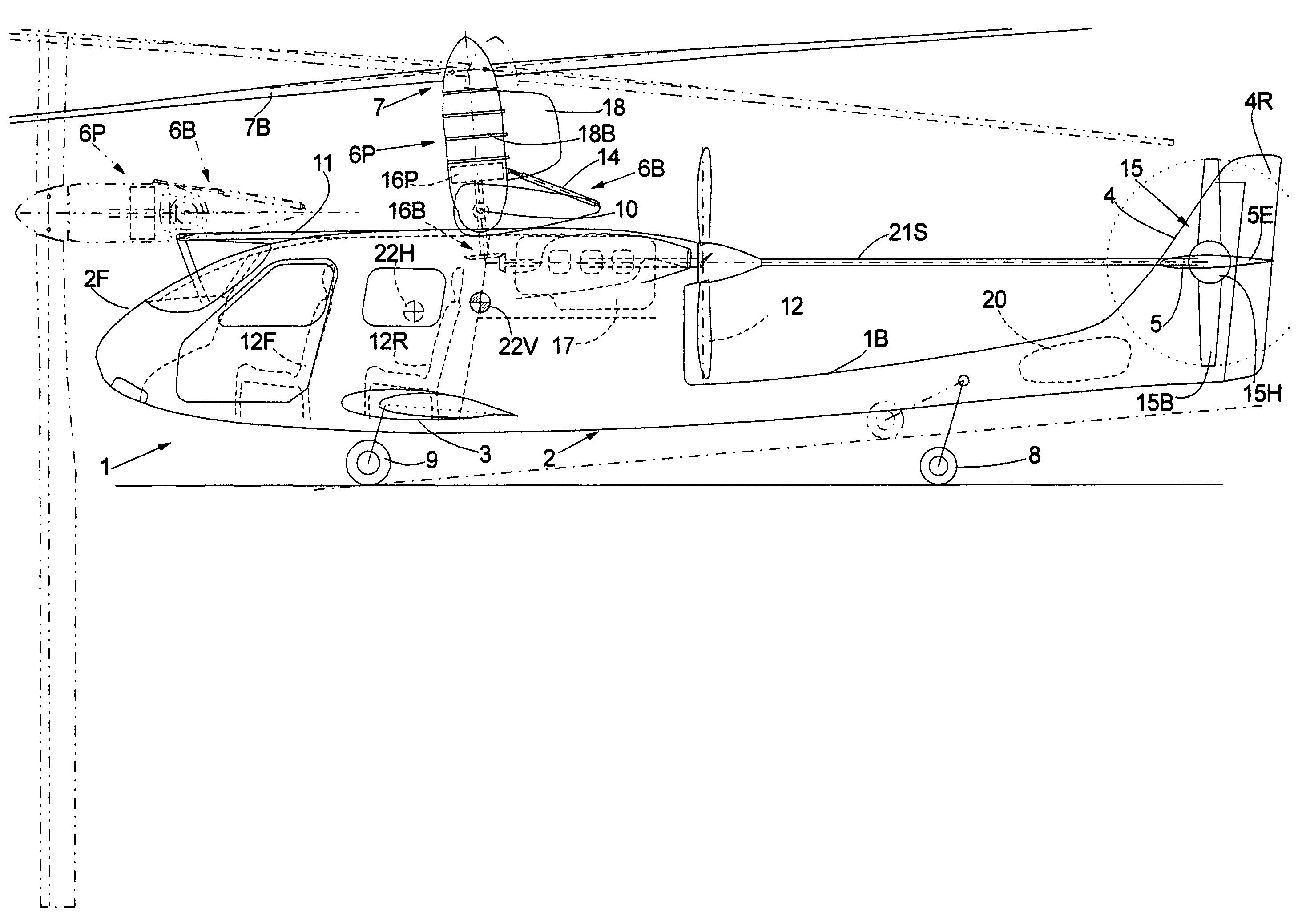
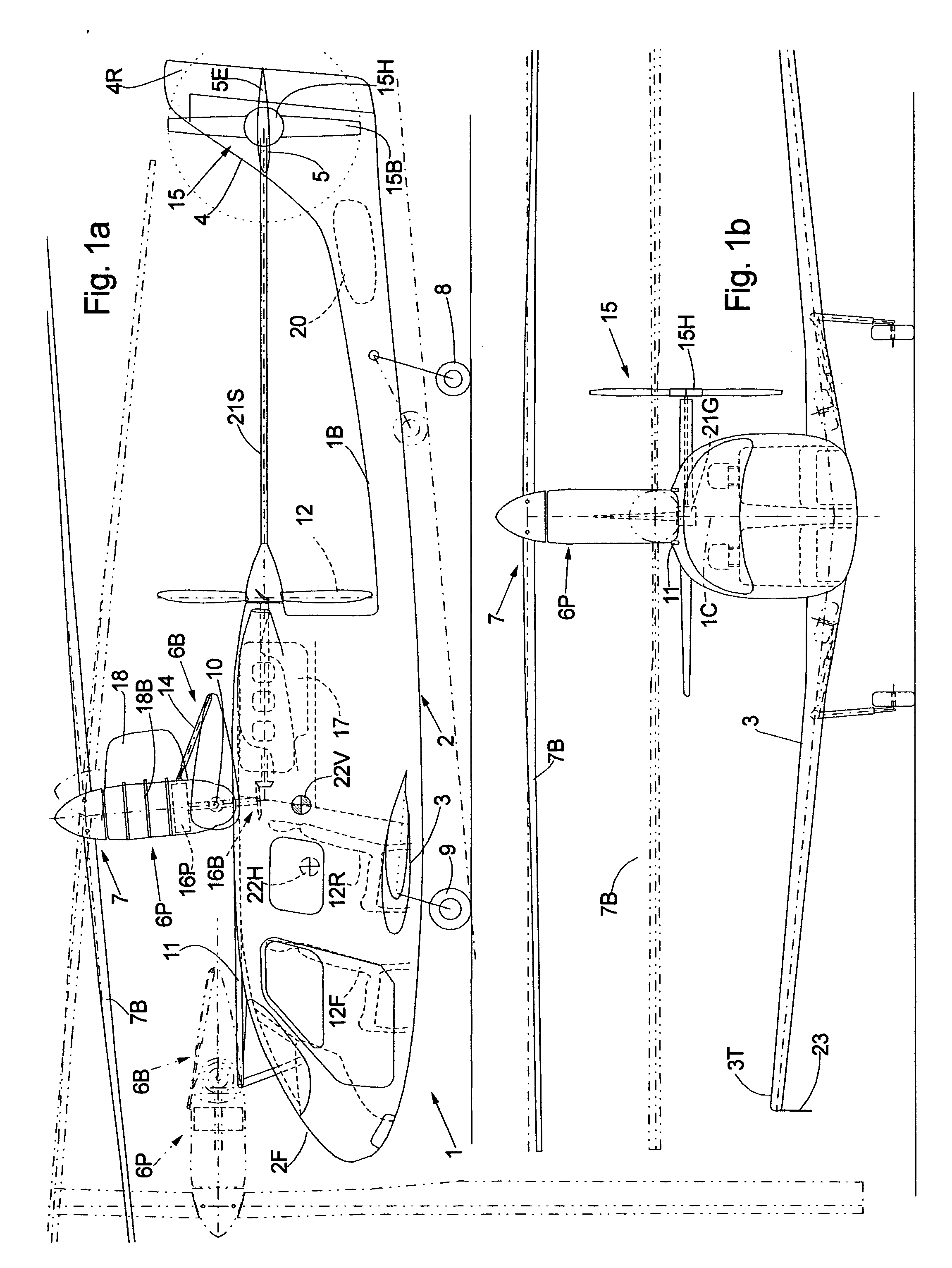
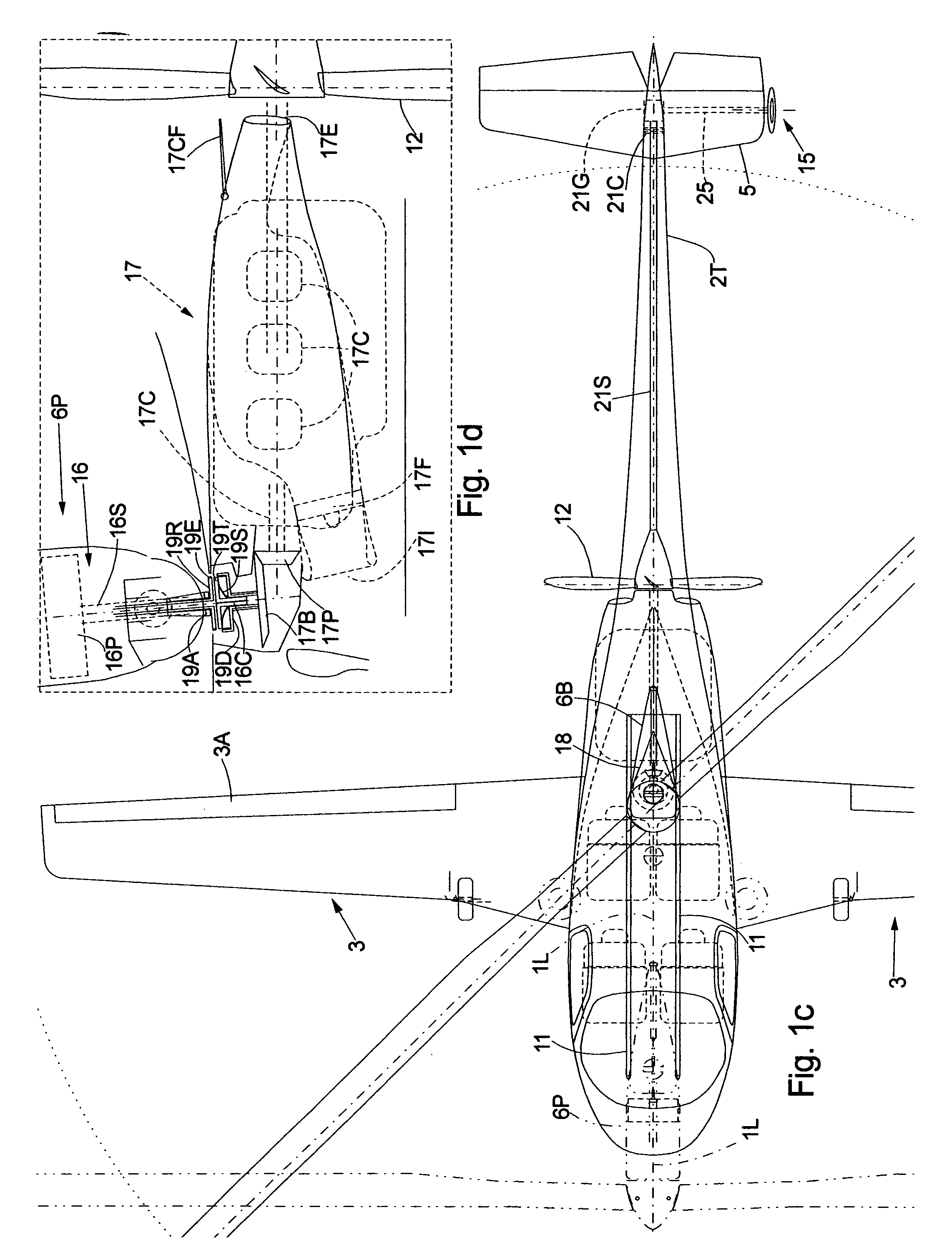
[0026] Referring to FIG. 1a there is shown a 4-seat convertiplane designated in its entirety by reference numeral 1, with a fuselage 2, a pair of wings 3, conventional landing gear arrangement with a retractable rear wheel 8 and a pair of retractable main wheels 9, vertical fin 4 with rudder 4r, and a horizontal stabilizer 5 with elevator 5e as in conventional airplane arrangement. For a low Center of Gravity (CG) 22V with respect to the ground, a cantilever low wing configuration is selected. For motive power during cruising flight mode, a single conventional aircraft engine 17 mounted aft of the cabin directly driving a 4-blade pusher propeller unit 12 . Propeller unit 12 is of variable-pitch design capable of zero pitch during the hovering mode and is featherable for maximum gliding efficiency in case of engine failure. Engine 17 is also connected to a bevel gear reduction unit 16B for vertical transfer of rotational power from the engine 17 to transmission 16P fo...


PUM


Abstract

A single-tilt-rotor VTOL airplanes have a tiltable rotor attached to an elongated power pod containing the collective and cyclical pitch mechanism, and transmission. The power pod is pivotably attached to a base that is slidably mounted on a pair of slotted guide beams attached on top of the roof of the fuselage. The guide beams run longitudinally from the front of the aircraft to past the center of gravity (CG) of the aircraft in order to transport the power pod from the front section to the center section when converting from the horizontal cruising mode to the VTOL mode. In the horizontal cruising mode, the power pod perched horizontally on top of the fuselage front section with sufficient clearance for the rotor to rotate in front of the aircraft. Upon transitioning to the VTOL mode, a telescopic actuator is used to pivot the power pod vertically while a cable-winch system is used to move the entire power pod and base assembly rearwardly to stop at the center of gravity of the aircraft, and vice versa, thus allowing the power pod to travel significantly rearward and forward as required for proper balancing of vertical lift as the power pod pivots 90 degrees during transition from VTOL mode to the cruising mode. A single piston engine, or a single or pair of turbofan engines, mounted slightly to the rear of the CG, have drive shafts that can be clutched and mated onto respective receiving shaft from the transmission within the power pod in order to power the tiltable rotor. The engine is also attached to a propeller for horizontal propulsion, or if turbofan engines are used, jet thrust is generated for horizontal cruise. A small anti-torque rotor or ducted fan toward the tail of the aircraft is mechanically coupled to the engine via a drive shaft to provide the necessary side-way thrust to overcome the main rotor's torque. In the horizontal cruising mode, the tiltable rotor is allowed to windmill slowly at a minimum rotational speed necessary to maintain the integrity of the rotor blades. The same propulsion principle can be applied to VTOL airplanes having more than one tiltable rotor, thereby can potentially increase the speed, range and reliability of current twin-wing-mounted-tilt-rotor aircraft. A pair of high-aspect-ratio wings on both sides of the fuselage provide highly efficient lift during cruising flight with very little induced drag. Conventional horizontal and vertical tail planes are used for directional stability in the cruising mode.

Description

CROSS-REFERENCE TO RELATED APPLICATION [0001] This application claims benefit of Provisional Application Ser. No. 60 / 438,809 filed on Jan. 9, 2003 entitled “High Performance VTOL Convertiplanes.”BACKGROUND OF THE INVENTION [0002] 1. Field of the Invention [0003] This invention pertains to vertical takeoff and landing (VTOL) airplane. More specifically, it pertains to a type of tilt-rotor VTOL airplane wherein large diameter helicopter-type of rotor is used for vertical lift, and which may be tilted 90 degrees forward during cruising flight when the aircraft is supported by conventional wings. In this invention, there is at least one large tiltable rotor attached to the aircraft provide vertical lift when the rotor is pointed upward and a separate means for providing horizontal thrust during cruise when the tiltable rotor is pointed 90 degrees horizontal, during which phase, the tiltable rotor is slowed down and is allowed to rotate at a minimum rotational rate adequate for maintaini...

Claims


Application Information

Patent Timeline
IPC IPC(8): B64C27/26B64C27/28
CPCB64C27/28B64C27/26
Inventor PHAM, ROGER N.
Owner PHAM ROGER N
Why Eureka
Try Eureka