Method and apparatus for manufacturing plastic optical transmission medium

a technology of optical transmission medium and manufacturing method, which is applied in the direction of instruments, other domestic objects, optical elements, etc., can solve the problems of inability to commercialize, inability to manufacture methods, and inability to achieve commercialization. commercially viable, reduce the effect of density fluctuations

Inactive Publication Date: 2005-03-24
NANOPTICS
View PDF27 Cites 28 Cited by
  • Summary
  • Abstract
  • Description
  • Claims
  • Application Information

AI Technical Summary

Benefits of technology

Stress may be created in the graded index fiber, for example in the form of radial or longitudinal mechanical stress. The stress can be induced by, for example, the fiber cooling and / or from drawing the fiber. Such stresses may create density fluctuations in the fiber material which can scatter the light and reduce light transmission. The subject invention can incorporate a method of continuous annealing of the fiber to reduce such density fluctuations, in order to enhance light transmission.
The subject invention can involve a method of on-line control of the refractive index profile of the fiber. The precise shape of this profile determines the communication bandwidth of the fiber. The subject method can reduce, or minimize, the diffusive tail of the profile, permitting very high bandwidth of the product and good light transmission.

Problems solved by technology

With respect to these fabrication methods, the rate of fiber production is no more than about one meter per minute and, therefore, these fabrication methods are not commercially viable.
However, the speed is very limited at which the desired fiber, with 0.2 mm to 1.0 mm diameter, can be drawn.
As a result, it is not a commercially viable process.
Nevertheless, the high cost of both the material and preform production process, coupled with the moderate fiber production rate mitigate against this process becoming commercially acceptable.
Previous attempts to extrude perfluorinated polymer (such as Teflon AF and CYTOP®) fiber have been performed at typical temperatures of at least 250° C., and in some cases 300° C., and have resulted in excessive light loss (typically >100 dB / km) and in one case, in the range 20-30 dB / km).
U.S. patent application 200201005102 (Blyler, LL 2002) disclosed that “conventional extrusion techniques, e.g., screw extruders, tended to introduce an undesirable amount of particulate contaminants which increased the (light) loss of the drawn fiber.” The high chemical reactivity between degradation products from perfluorinated materials when subjected to high temperatures and metals is a well known challenge to processing technologies.
Thus, excessive light attenuation in extruded perfluorinated optical fiber is an unresolved problem in the art.
Prior art perfluorinated GRIN fiber has been limited in its ability to transmit data at high rate.
The achieved bandwidth has been limited by the less than optimal shape of the transverse GRIN profile.
Thus, light rays at large radius in the fiber experience substantial time dispersion which limits the achievable bandwidth.
In summary, there remain several major problems in the production of perfluorinated GRIN plastic optical fiber.
The preform route to fiber manufacture produces the fiber at less than desirable optical transmission, and at less than desirable manufacturing speed.
The extrusion production route provides fiber at an adequate rate, less than desirable transmission bandwidth and less than desirable optical transmission.

Method used


Image

  • Method and apparatus for manufacturing plastic optical transmission medium
  • Method and apparatus for manufacturing plastic optical transmission medium
  • Method and apparatus for manufacturing plastic optical transmission medium

Examples


second embodiment

In the subject invention, an index-lowering additive is added to the cladding polymer, with no other additives used.

third embodiment

In the subject invention an index-raising additive is added to the core polymer and an index-lowering additive is added to the cladding polymer, with no other additive used.

fourth embodiment

In this invention, an index-raising additive is added to the core, an index-lowering additive is added to the cladding polymer, and an index-lowering additive is added to the coat polymer.

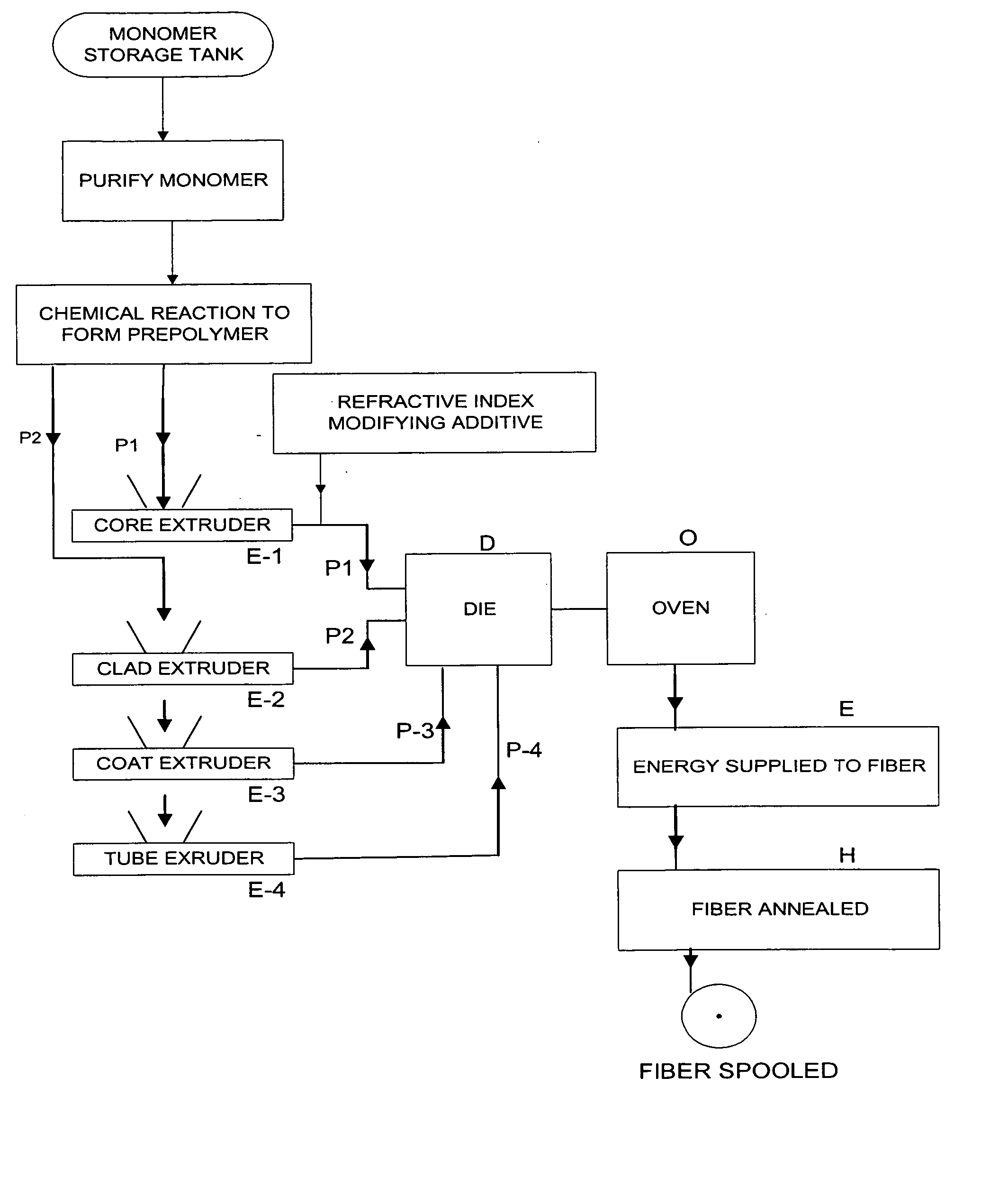
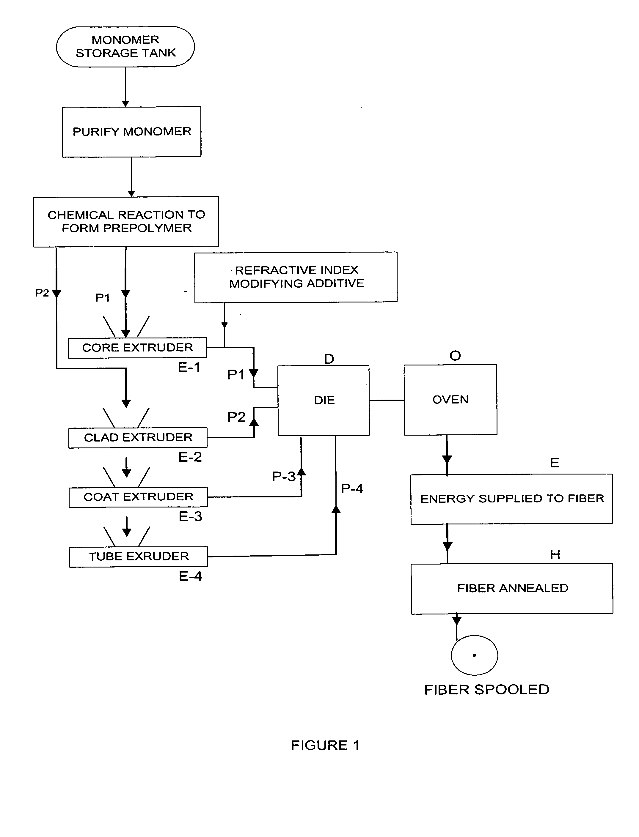
The subject invention pertains to a method of fiber manufacture which permits a light attenuation of ≦10 db / km at 850 nm wavelength. The light loss of existing commercial LUCINA fiber is typically 20 to 30 dB / km at 850 nm.

The subject invention also relates to a method to simultaneously produce a fiber whose GRIN profile is stable up to 85° C. and has an optical attenuation at 850 nm of ≦10 dB / km.

A reasonable criterion for immobilization of additives in the polymer is that the maximum operating temperature Top, of the fiber should be at least 20° C. below the glass transition temperature, TgPlasticized, of the plasticized polymer. This may be written as:

TgPlasticized≧Top+20° C.

Different additives can cause quite different reductions in the glass transition temperature of the pure polymer who...


PUM

PropertyMeasurementUnit
glass transition temperaturesaaaaaaaaaa
temperatureaaaaaaaaaa

Abstract

The subject invention pertains to a method for high speed, continuous manufacture of graded refractive index polymer optical fiber. The subject fiber material may be organic or perfluorinated. The subject method can include first forming energy activatable prepolymer compositions containing additives. The prepolymer compositions can be extruded at low temperature through a multi-annular die and surrounded by a co-extruded concentric melt stream which forms a tube with good structural integrity. The prepolymer compositions contained in the tube can be maintained at a temperature for a time sufficient to form the desired graded index profile. Energy can be delivered to the prepolymer compositions which can cause an irreversible chemical transformation and forms a mechanically and thermally stable polymer. A continuous process of thermal annealing of the fiber can be used to minimize residual stress. Multiple fibers may be produced simultaneously in a variety of physical configurations.

Description

BACKGROUND OF THE INVENTION Fabrication of graded-refractive-index (GRIN) optical fiber is well known. For example, U.S. Pat. No. 5,760,139 and U.S. Pat. No. 5,783,636 disclose numerous methods for fabricating a graded-refractive-index optical fiber. In such optical fiber, a dopant is often distributed in a polymer so as to have a concentration gradient in the direction from the center to the periphery. Typically, the dopant is a material having a higher refractive index than the fluoropolymer and the dopant is so distributed as to have a concentration gradient such that the concentration of the dopant decreases in the direction from the center of the optical fiber to the periphery. Hence, a graded refractive index optical fiber can be produced by arranging the dopant at the center and diffusing the dopant toward the periphery. In other cases, a graded refractive index optical fiber is formed wherein the dopant is a material having a lower refractive index than the fluoropolymer, a...

Claims


Application Information

Patent Timeline
Patent Type & Authority Applications(United States)
IPC IPC(8): B29D11/00G02B1/04G02B6/44
CPCB29D11/00682G02B6/4403G02B6/02038G02B1/045
Inventor WALKER, JAMES K.
Owner NANOPTICS
Why Eureka
Try Eureka