

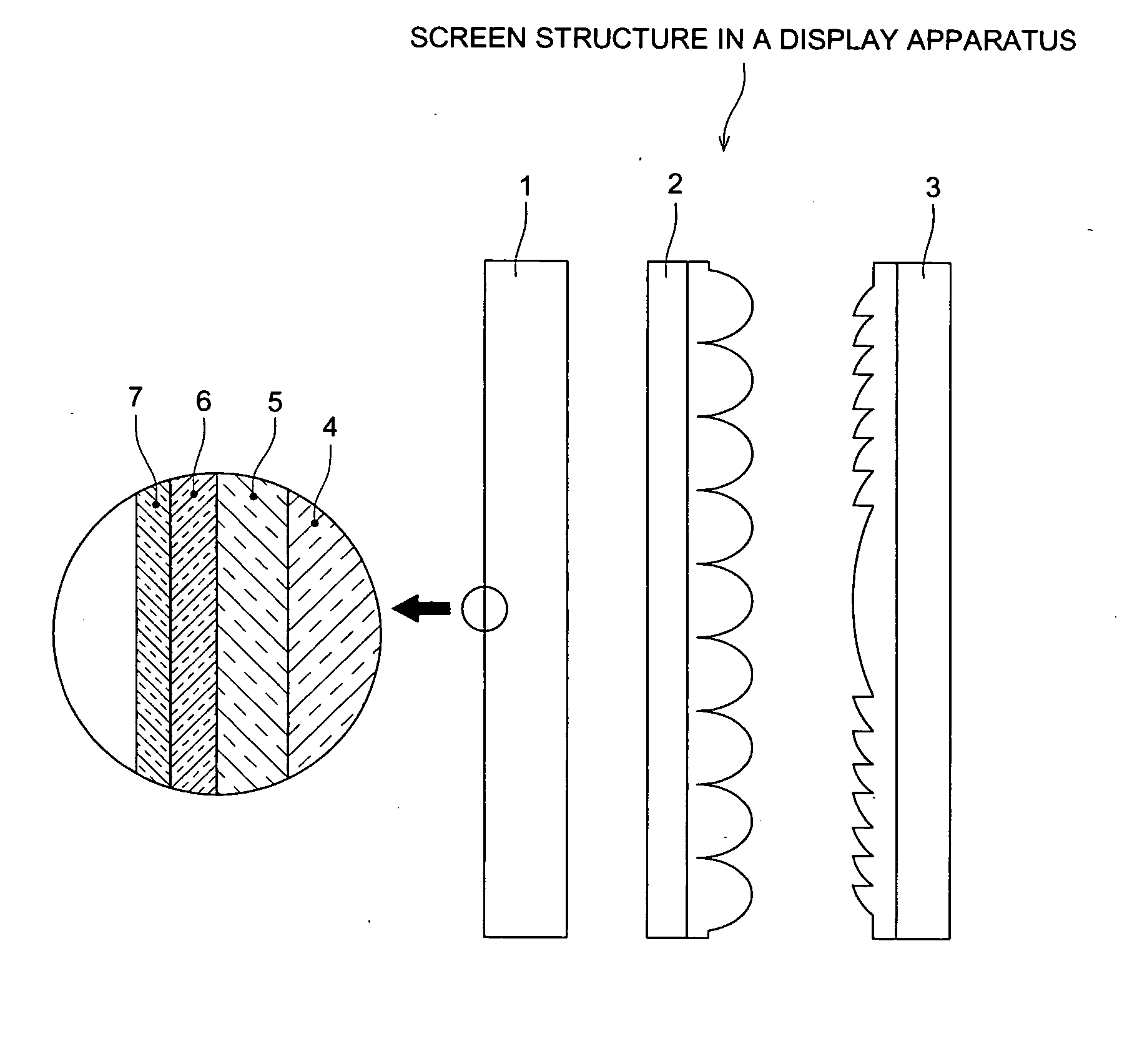
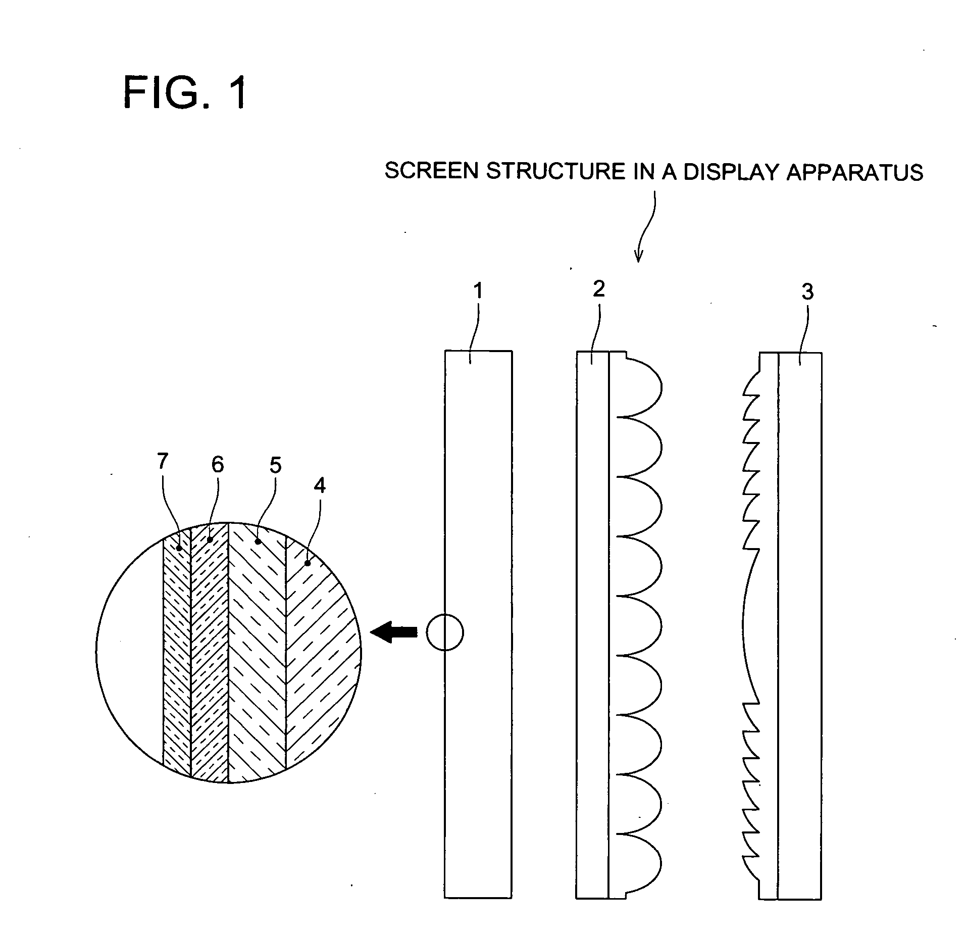
Display front plane, display linticular lens, and display fresnel lens
a technology of lenticular lens and display, which is applied in the field of front plane, lenticular lens, or fresnel lens, can solve the problems of whitish screen surface, inability to easily watch pictures on the screen, and inability to reduce so as to achieve the effect of reducing the number of viewers caught by the display, reducing the effect of reflection and uniform coat thickness
- Summary
- Abstract
- Description
- Claims
- Application Information
AI Technical Summary
Benefits of technology
Problems solved by technology
Method used
Image

Examples
example 1
Front Plane
[Manufacture of Electrode]
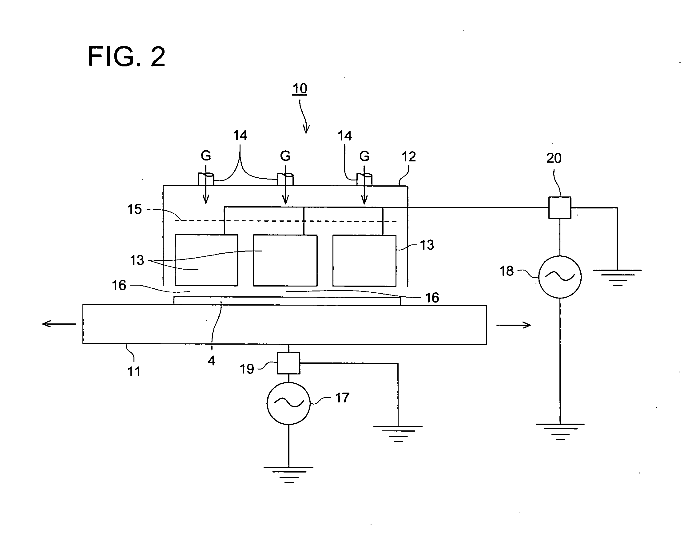
A stage electrode and a rectangular cylinder-shaped electrode were manufactured as follows. Those stage electrode and rectangular cylinder-shaped electrode made of titanium alloy T64 with hollow jackets were manufactured as described below. A high dense and high adhesive alumina thermal spray film was coated on the surfaces facing mutually between a stage electrode and a rectangular cylinder-shaped electrode by the atmospheric pressure plasma method. After coating thereafter the solution which is tetramethoxysilane diluted by ethylacetate and then drying, a curing operation with ultraviolet irradiation and a sealing treatment took place. Coated dielectric surfaces were polished and smoothed and they were processed so that Rmax may come to 5 μm. The percentage of porosity of the final dielectric was 5 vol %. SiOx content in dielectric layers at this time was 75 mol %. Thickness of the final dielectric and relative permittivity of the dielectric...
example 2
Front Plane
All were the same items as in Example 1 except for the changes to the first and the second high frequency electric fields shown in Table 2 and the installation of the first and the second filters and Samples No. 17-No. 23 were prepared.
Samples No. 17-No. 23 were evaluated as described above and results were shown in Table 2.
TABLE 2The first electric fieldThe second electric fieldElectricElectricfieldPowerThefieldPowerTheEvaluation resultSam-PowerFrequencyintensitydensityfirstPowerFrequencyintensitydensitysecondStateplesourceω1V1(W / filtersourceω2V2(W / filterofRefractiveNo.type(Hz)(kV / mm)cm2)usagetype(Hz)(kV / mm)cm2)usagedischargeindexRemark17A2 5k121Condenser 1B313.56M0.810Coil 1A2.33Inv.18A5100k81Condenser 1B313.56M0.810Coil 1A2.32Inv.19A2 5k121Coil 1B1 800k1.210Coil 1A2.22Inv.20A5100k81Coil 1B1 800k1.210Coil 1A2.28Inv.21B1800k1.21Coil 2B1 800k1.210Coil 2C*1Comp.22B313.56M 0.81Not inNot in useNot inC*1Comp.useuse23A4 50k101Not inNot in useNot inA1.63Comp.useuse
Con...
example 3
Front Plane
As the base material, a commercially available PMMA plate with 2 mm in thickness on which a hard coat film is formed was used and as an equipment, the same atmospheric pressure plasma discharge treatment equipment as in FIG. 2 was used. The base material was placed on a stage electrode and an anti-reflection film was deposited. Specifically, a stage electrode was reciprocated and a front plane on which an anti-reflection film is deposited with the following laminated structure composed of the base material / a hard coat layer / a high refractive index layer / a low refractive index layer / a high refractive index layer / a low refractive index layer in the order described here (Samples No. 24-27) was manufactured by laminating a high refractive index and a low refractive index layers one after the other on a hard coat film.
[Manufacture of Front Plane on Which Anti-Reflection Film is Deposited]
In the middle of plasma discharging, a temperature adjustment was made in such a way ...
PUM
| Property | Measurement | Unit |
|---|---|---|
| Thickness | aaaaa | aaaaa |
| Volume | aaaaa | aaaaa |
| Frequency | aaaaa | aaaaa |
Abstract
Description
Claims
Application Information