
Method of manufacturing an active cooling panel out of thermostructural composite material

a technology active cooling panels, which is applied in the direction of lighting and heating apparatus, combustion process, soldering media, etc., can solve the problems of limiting the capacity to cool the exposed surface, unsuitable for use on its own, and residual porosity of thermostructural composite materials, so as to achieve the effect of effective and durabl

Inactive Publication Date: 2005-04-14
SNECMA PROPULSION SOLIDE
View PDF17 Cites 29 Cited by
  • Summary
  • Abstract
  • Description
  • Claims
  • Application Information

AI Technical Summary

Benefits of technology

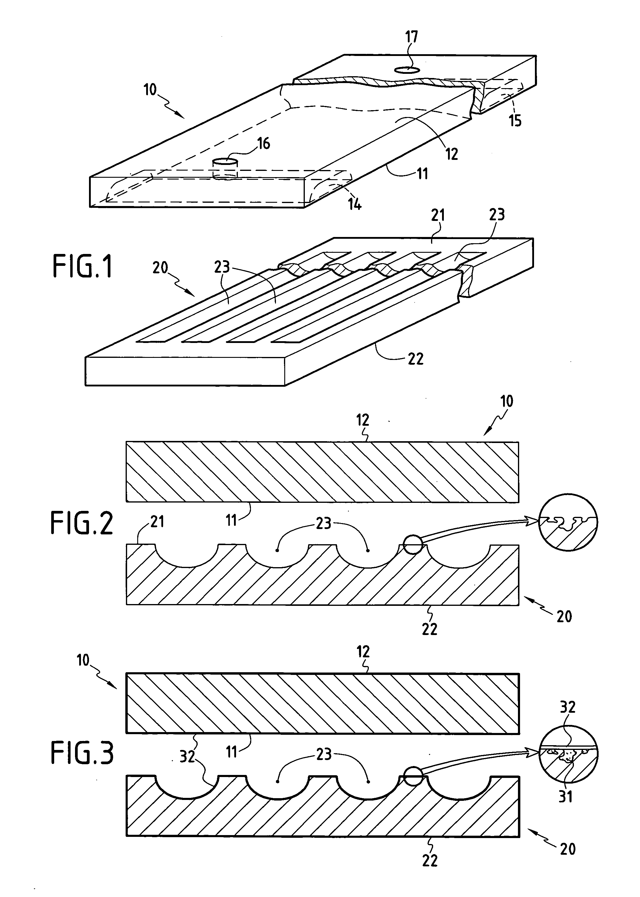
[0014] An object of the invention is to provide a method of manufacturing an active cooling panel out of thermostructural composite material presenting leakproofing that is effective and durable for a fluid flowing in internal passages of the panel.
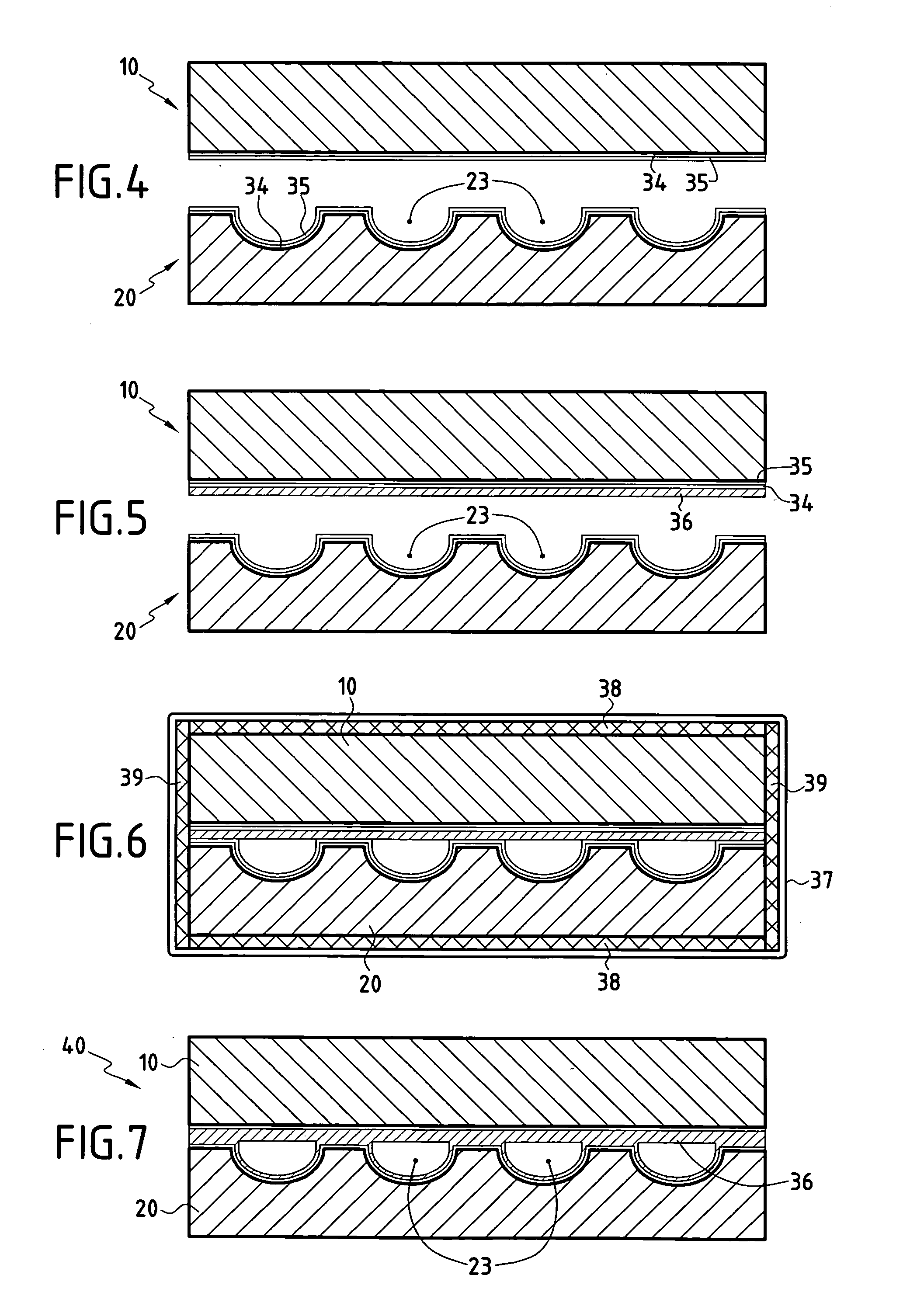
[0017] This kind of bonding presents the advantage of avoiding the use of a liquid as is required for brazing, and the temperature required is lower than that required for brazing. Continuity of the metal coating is thus better preserved.
[0027] According to an advantageous feature of the invention, prior to forming the metal coatings on said inside faces of the parts to be assembled together, treatment is performed to reduce the surface porosity of the thermostructural composite material on at least one of said inside faces.

Problems solved by technology

Whatever the densification method used, thermostructural composite materials present residual porosity so they are unsuitable for use on their own in forming cooling panels having internal fluid-conveying passages, since the walls of such passages are not leakproof.
In addition, the length of the path along which heat travels through the graphite plate and the metal plate puts a limit on capacity to cool the exposed surface.
The second and third solutions are satisfactory in terms of mass and of shortening heat flow path length, but leakage problems can arise due to the metal lining or the brazing cracking following repeated exposure to very high temperatures.

Method used


Image

  • Method of manufacturing an active cooling panel out of thermostructural composite material
  • Method of manufacturing an active cooling panel out of thermostructural composite material
  • Method of manufacturing an active cooling panel out of thermostructural composite material

Examples


example

[0083] Parts 10 and 20 similar to those shown in FIG. 1 were made of C / SiC thermostructural composite material, with the channels and the manifolds being formed by machining.

[0084] The porosity of the inside surfaces of the parts was reduced by brushing onto them a composition containing an SiC powder of mean grain size equal to about 9 microns (μm) in a PCS solution in xylene. After drying in air, the PCS was cross-linked at about 350° C. and then transformed into SiC by raising the temperature to about 900° C. A thin coating of SiC having thickness of about 100 μm was then deposited by chemical vapor infiltration, with the coating then being formed over the entire outside surface of each of the parts 10, 20 and not only over the inside faces of the parts. In combination with the residue of ceramizing the PCS associated with the SiC powder, the SiC coating contributes to achieving an effective reduction of porosity.

[0085] Metal deposits of rhenium and then of nickel were formed i...


PUM

PropertyMeasurementUnit
temperatureaaaaaaaaaa
thicknessaaaaaaaaaa

Abstract

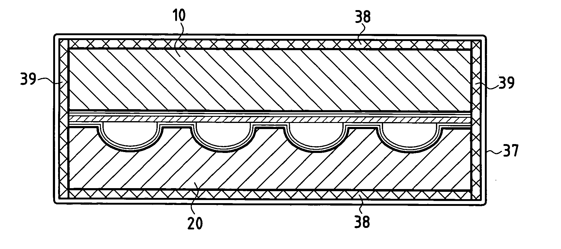
A metal coating is formed on the inside face of a first thermostructural composite material part presenting indentations forming channels, and also on the inside face of a second thermostructural composite material part for being applied against the inside face of the first part, and the first and second parts are assembled together by bonding said inside faces together by hot compression, in particular by hot isostatic pressing, thereby obtaining a thermostructural composite material cooling panel having integrated fluid flow channels. The invention is applicable to making heat exchanger walls such as the walls of combustion chambers in aircraft engines, or the diverging portions of rocket engines, or plasma confinement chambers in nuclear fusion reactors.

Description

BACKGROUND OF THE INVENTION [0001] The present invention relates to manufacturing an active ooling panel out of thermostructural composite material. [0002] The term “active cooling panel” is used herein to mean a panel having a cooling fluid passing therethrough for the purpose of taking away the heat received by the panel being exposed to high temperature or high heat flux. [0003] The term “thermostructural composite material” is used herein to mean a composite material having mechanical properties which make it suitable for constituting structural elements and having the ability to conserve these mechanical properties at high temperature. Thermostructural composite materials are typically carbon-carbon (C / C) type composite material comprising a reinforcing structure made of carbon fibers densified by a matrix of carbon, and ceramic matrix composite (CMC) materials comprising a reinforcing structure of refractory fibers (in particular carbon fibers or ceramic fibers) densified by a...

Claims


Application Information

Patent Timeline
Patent Type & Authority Applications(United States)
IPC IPC(8): F28F21/00B23K20/00B23K20/16B23K101/18F02K9/64F02K9/97F23R3/00F28F3/12F28F21/08
CPCF02K9/64F02K9/972F02K9/974F23R3/005F28F21/087F28D2021/0078F28F3/12F28F21/085F23R3/007Y02E30/10F02K1/822F23M5/08F28F21/08
Inventor LARRIEU, JEAN-MICHELUHRIG, GILLESTHEBAULT, JACQUESBOUQUET, CLEMENT
Owner SNECMA PROPULSION SOLIDE
Learn More