Carbon nanotube and process for producing the same

a carbon nanotube and process technology, applied in the field of carbon nanotubes, can solve the problems of increased production costs, low productivity, unsuitable as a mass production method of carbon nanotubes, etc., and achieve the effect of simplifying the process for producing carbon nanotubes

Inactive Publication Date: 2005-05-12
MITSUBISHI CHEM CORP
View PDF11 Cites 57 Cited by
  • Summary
  • Abstract
  • Description
  • Claims
  • Application Information

AI Technical Summary

Benefits of technology

[0100] In addition, in the present invention, the respective raw materials including the core particles and the carbon precursor resin preferably have such a spinning property that they can be melt-spun into fibers having a length of not less than 5 cm under the same conditions (under actual melt-spinning conditions). Namely, in order to achieve reduction in diameter of the carbon nanotube, more specifically reduce the outer diameter thereof to not more than 500 nm, it is important to appropriately select these raw materials. The proper selection of the raw materials allows the particles obtained therefrom to be stretched and elongated along the fiber axis direction in an extremely suitable manner, thereby achieving reduction in diameter of the resultant carbon nanotube. More preferably, the respective raw materials have such a spinning property that they can be melt-spun into fibers having a length of not less than 10 cm.
[0107] Also, the matrix resin and the resin for the core particles may be identical to each other or may be in combination of different kinds of resins. However, when the resin for the core particles is the same as the matrix resin, the process for production of the carbon nanotube can be simplified, resulting in industrially advantageous process.

Problems solved by technology

However, the arc discharge methods and laser evaporation methods suffer from a low productivity and increased production costs, therefore, are unsuitable as a method for mass production of carbon nanotubes.
On the other hand, although the gas phase methods are suitable for the mass production of carbon nanotubes, there arises such a problem that since transition metals such as Fe, Co and Ni are used as a catalyst in the production process, these metal components are inevitably mixed in resultant products in as large an amount as several percents by weight, thereby requiring post-treatments for removing the metal components therefrom.
Also, in the gas phase methods, there arises such a drawback that side reactions tend to be caused during the production reaction owing to the presence of the metal components, resulting in inclusion of a large amount of amorphous carbon components other than carbon nanotube in the obtained product.
Therefore, the gas phase methods have problems such as high production costs when applied to the mass production techniques at an industrial level.
For this reason, it is usually difficult to introduce functional groups to the surface of the carbon nanotubes.
In such a method of introducing the functional groups only to the tip end of the carbon nanotube, since the number of functional groups which can be introduced to the whole carbon nanotubes is restricted, it may be difficult to sufficiently solubilize elongated carbon nanotubes.
However, in the case of such carbon nanotubes having a low crystallinity as a whole, since large portions of the carbon nanotubes including even inside portions thereof, are low in crystallinity, it is easily suggested that the carbon nanotubes tend to lose advantages of the high-crystallinity carbon nanotubes such as a high conductivity and a high strength.
Therefore, the above proposal has many technical problems as compared to the methods of introducing the functional groups onto the surface of carbon nanotubes.
In addition, even if the functional groups are introduced into the central portion of carbon nanotubes, it is hardly expected that such carbon nanotubes show the same effects (such as solubilization) as those of the carbon nanotubes in which the functional groups are introduced into an outer surface thereof.

Method used


Image

  • Carbon nanotube and process for producing the same
  • Carbon nanotube and process for producing the same
  • Carbon nanotube and process for producing the same

Examples


example 1

[0119] 35 ml of a MMA monomer and 35 mg of potassium persulfate (hereinafter referred to as “KPS”) as a radical polymerization initiator were added to 350 ml of deionized water and mixed together, and the resultant mixture was bubbled with a nitrogen gas for 30 minutes. Thereafter, the mixture was reacted at 70° C. for 4.5 hours and then at 80° C. for 30 minutes while stirring at 300 rpm, thereby obtaining a suspension containing PMMA core particles.

[0120] 90 ml of the thus obtained suspension was mixed with 4 ml of an acrylonitrile monomer, 5 mg of KPS and 270 ml of deionized water, and the resultant mixture was bubbled with a nitrogen gas for 30 minutes. Thereafter, the mixture was reacted at 70° C. for 7.5 hours and then at 80° C. for 30 minutes while stirring at 300 rpm, thereby obtaining a suspension containing PMMA core particles coated with a carbon precursor resin.

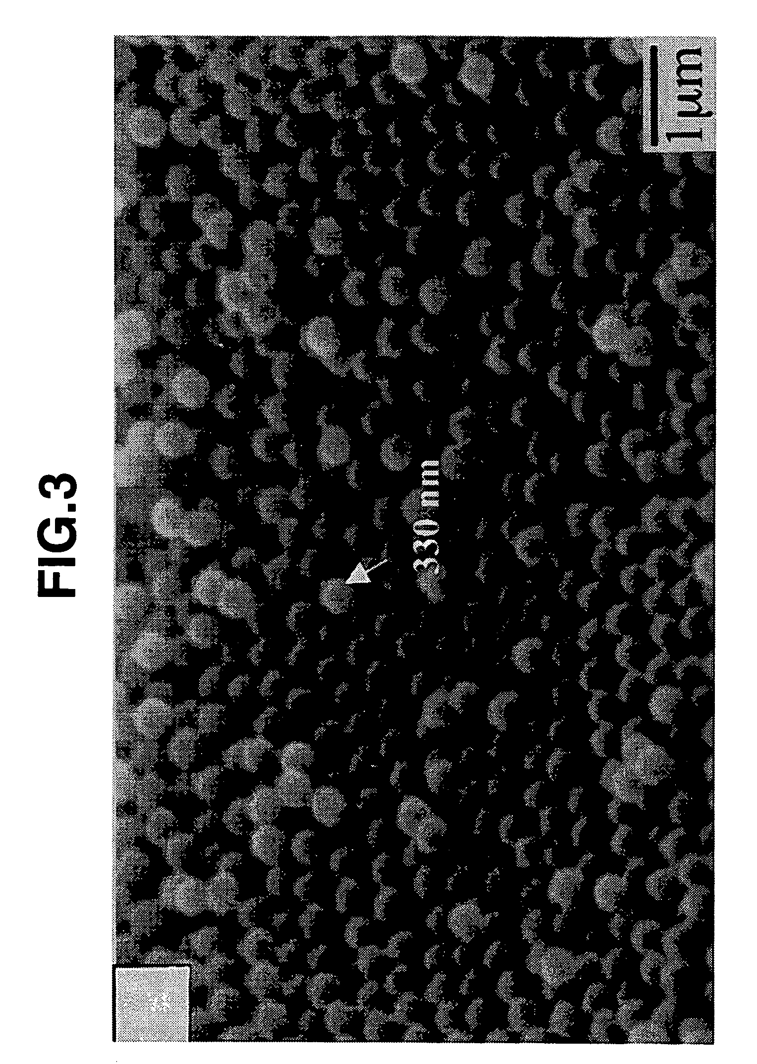
[0121] In FIG. 3, there is shown a SEM (scanning electron microscope) image (used instead of drawing) of avera...

example 2

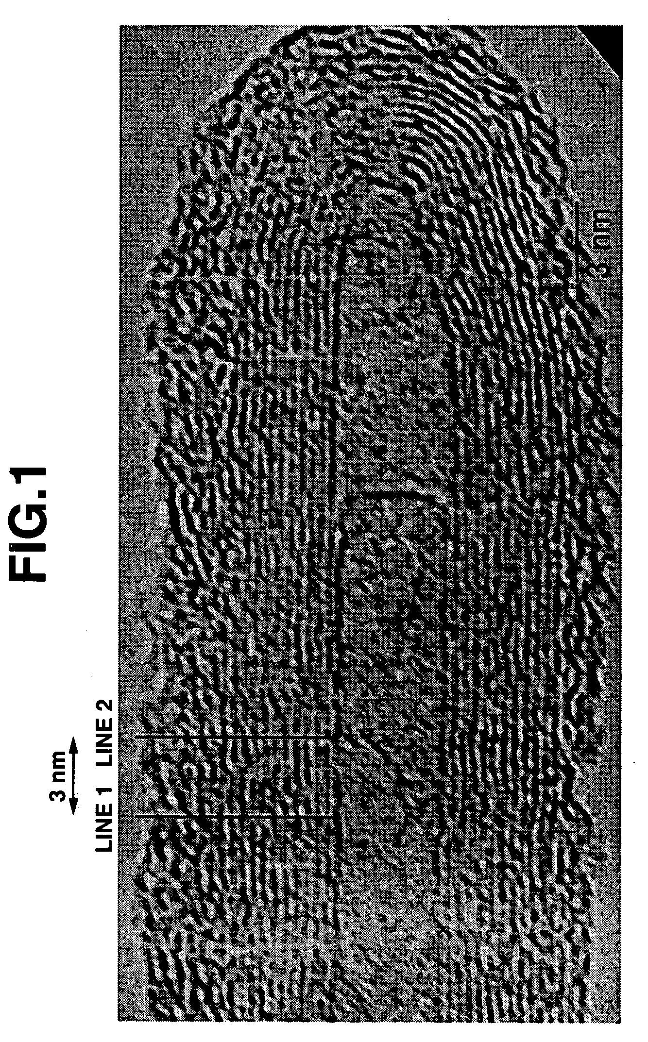
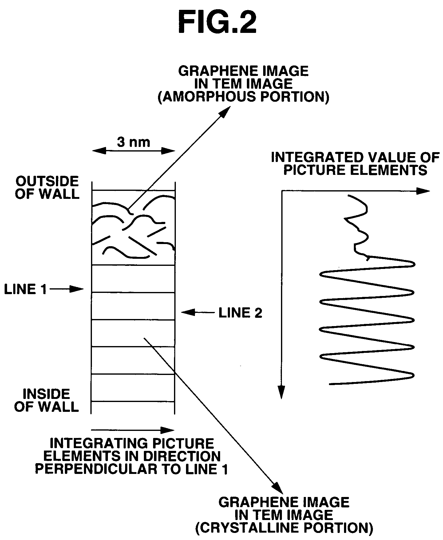
[0125] The same procedure as defined in Example 1 was conducted except that the acrylonitrile added upon polymerization for production of the carbon precursor resin was used in an amount of 2 ml, and the carbonization treatment was performed at 900° C. for 30 minutes, thereby producing carbon nanotubes. As a result, it was confirmed that the thus obtained carbon nanotubes had an average particle diameter of 10 nm, an average central cavity diameter of 2.4 nm and an average wall thickness of about 4 nm. The TEM image (used instead of drawing) of the obtained average carbon nanotubes is shown in FIG. 7. As a result of observing the TEM image, it was confirmed that the wall of the respective carbon nanotubes had an outside region of an amorphous structure and an inside region of a crystalline structure made of graphene sheets. In addition, in the image, there were observed no shades due to metals contained in the carbon nanotubes, and there were further observed images showing the incl...

example 3

[0126] 35 ml of a MMA monomer and 35 mg of KPS as a radical polymerization initiator were added to 350 ml of deionized water and mixed together, and the resultant mixture was bubbled with a nitrogen gas for 30 minutes. Thereafter, the mixture was reacted at a temperature of 70 to 80° C. for 8 hours while stirring at 300 rpm, thereby obtaining a suspension containing PMMA particles.

[0127] 90 ml of the thus obtained suspension was mixed with 2 ml of an acrylonitrile monomer, 5 mg of KPS and 260 ml of deionized water, and the resultant mixture was bubbled with a nitrogen gas for 30 minutes. Thereafter, the mixture was reacted at a temperature of 70 to 80° C. for 8 hours while stirring at 300 rpm, thereby obtaining a suspension containing PMMA core particles coated with a carbon precursor resin. 350 ml of the thus obtained suspension was mixed with 35 ml of a MMA monomer, 5 mg of KPS and 350 ml of deionized water, and the resultant mixture was bubbled with a nitrogen gas for 30 minutes...


PUM

PropertyMeasurementUnit
lengthaaaaaaaaaa
lengthaaaaaaaaaa
thicknessaaaaaaaaaa

Abstract

The carbon nanotube of the present invention has an outer diameter of not more than 500 nm and a length of not less than 50 nm, and comprises a wall which is made of carbon and includes an outside region of an amorphous structure and an inside region of a crystalline structure. The carbon nanotube of the present invention is a novel carbon nanotube which allows functional groups to be readily bonded to the surface thereof since the outside region of the wall has an amorphous structure, and can exhibit a high electrical conductivity and a high strength since the inside region of the wall has a crystalline structure.

Description

TECHNICAL FIELD [0001] The present invention relates to a carbon nanotube and a process for producing the carbon nanotube. The “carbon nanotube” described herein means a hollow carbon fiber having an outer diameter of nanometer order and such a structure that a graphite layer (graphene sheet) made of a series of carbon 6-membered rings is rounded into a tubular shape. The carbon nanotube may be applied to electron emission materials, hydrogen-absorbing materials, adsorption-filtering materials, conductive materials, etc. BACKGROUND ART [0002] As conventionally known methods for producing carbon nanotubes, there have been proposed arc discharge methods, laser evaporation methods, gas phase methods (thermal CVD methods) or the like. More specifically, the arc discharge methods have been proposed, for example, in Japanese Patent Application Laid-open (KOKAI) Nos. 7-165406 and 7-197325, etc. The laser evaporation methods have been proposed, for example, in Japanese Patent Application La...

Claims


Application Information

Patent Timeline
Patent Type & Authority Applications(United States)
IPC IPC(8): C01B31/02D01F9/12D01F9/22
CPCB82Y30/00B82Y40/00C01B31/0226D01F9/22C01B2202/26C01B2202/34C01B2202/36C01B2202/22C01B32/16
Inventor OYA, ASAOHULICOVA, DENISAKURODA, SHINICHI
Owner MITSUBISHI CHEM CORP
Why Eureka
Try Eureka