
Dye-sensitized solar cell based on electrospun ultra-fine titanium dioxide fibers and fabrication method thereof

a technology of titanium dioxide and solar cells, applied in titanium dioxide, light-sensitive devices, electrolytic capacitors, etc., can solve the problems of non-liquid electrolyte infiltration, liquid electrolyte leakage, non-liquid electrolyte infiltration, etc., and achieve the effect of improving adhesiveness

Inactive Publication Date: 2005-05-26
KOREA INST OF SCI & TECH
View PDF4 Cites 59 Cited by
  • Summary
  • Abstract
  • Description
  • Claims
  • Application Information

AI Technical Summary

Benefits of technology

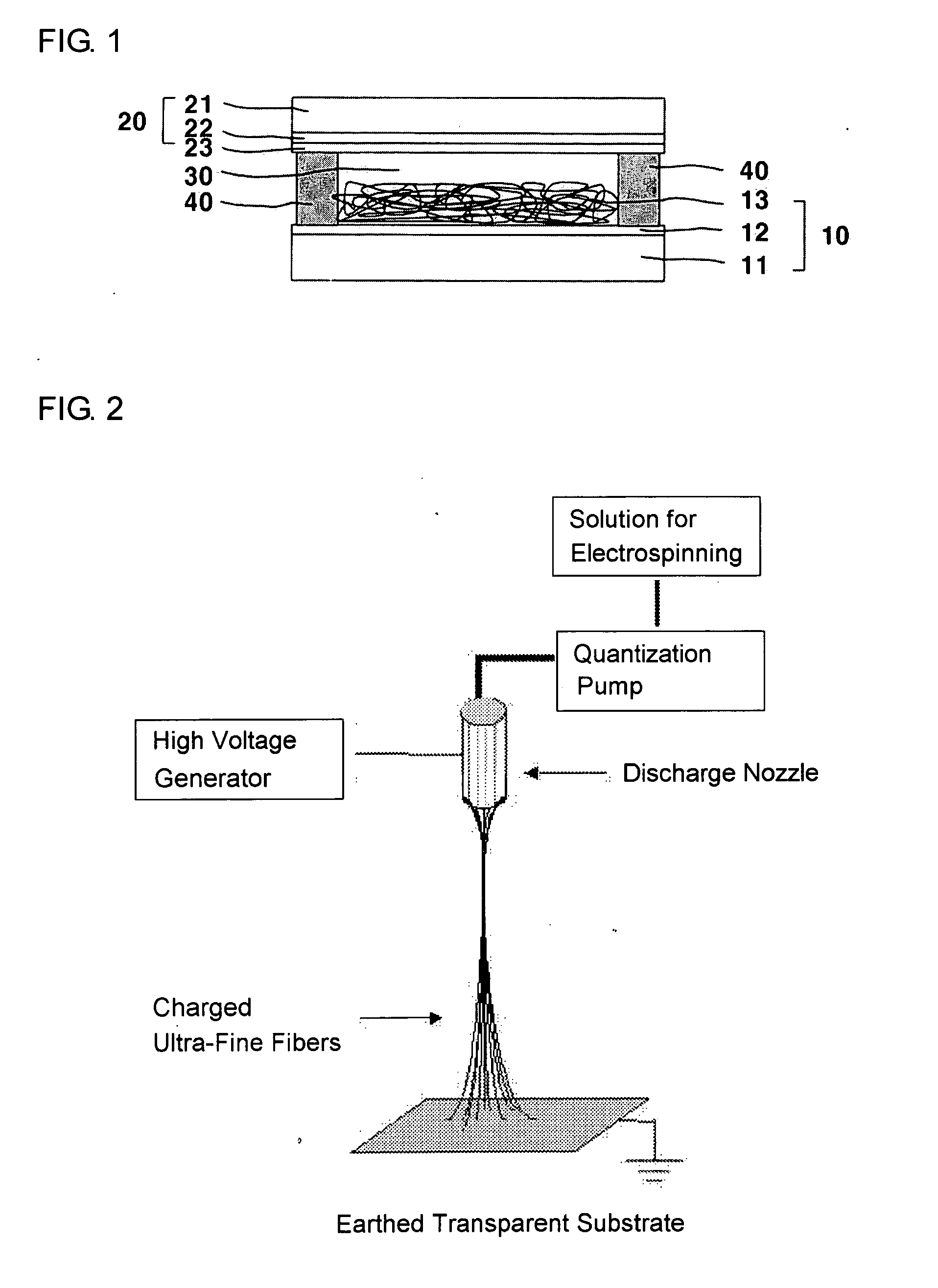
[0007] Therefore, one object of the present invention is to provide a dye-sensitized solar cell comprising a semiconductor electrode consisting of electrospun ultra-fine fibrous crystalline titanium dioxide, which can solve electron mobility problems throughout particles occurring in the conventional dye-sensitized solar cell using an electrode made of sintered nanocrystalline titanium dioxide, and which can also improve adhesiveness with solid electrolyte and element characteristics.

Problems solved by technology

However, because dye-sensitized solar cells provided until now include a liquid electrolyte, stability problems have been raised, and especially, because it is difficult for such solar cells to be sealed, the liquid electrolyte can be leaked or an electrochemical stability cannot be ensured in using the same for a long time.
However, while a liquid electrolyte can easily infiltrate throughout an entire electrode plate having a thickness of 10 μm or more which is fabricated by sintering nanocrystalline titanium dioxide particles, it is difficult for a non-liquid electrolyte to infiltrate into such electrode plate, and therefore, energy conversion efficiency is lowered for cells using a non-liquid electrolyte compared to those using a liquid electrolyte (Chem. Lett. 30, 26 (2001); 31, 948 (2002)).
Although a cell construction using a porous titanium dioxide thin film based on a sol-gel method or particles in rod shape has been proposed as a solution for such problems, it has been known that its performance is much inferior compared to the conventional nano-particle type.
Therefore, there are problems yet to be solved.

Method used


Image

  • Dye-sensitized solar cell based on electrospun ultra-fine titanium dioxide fibers and fabrication method thereof
  • Dye-sensitized solar cell based on electrospun ultra-fine titanium dioxide fibers and fabrication method thereof
  • Dye-sensitized solar cell based on electrospun ultra-fine titanium dioxide fibers and fabrication method thereof

Examples


example

Example 1

Fabrication of an Electrospun Titanium Dioxide Fiber Layer

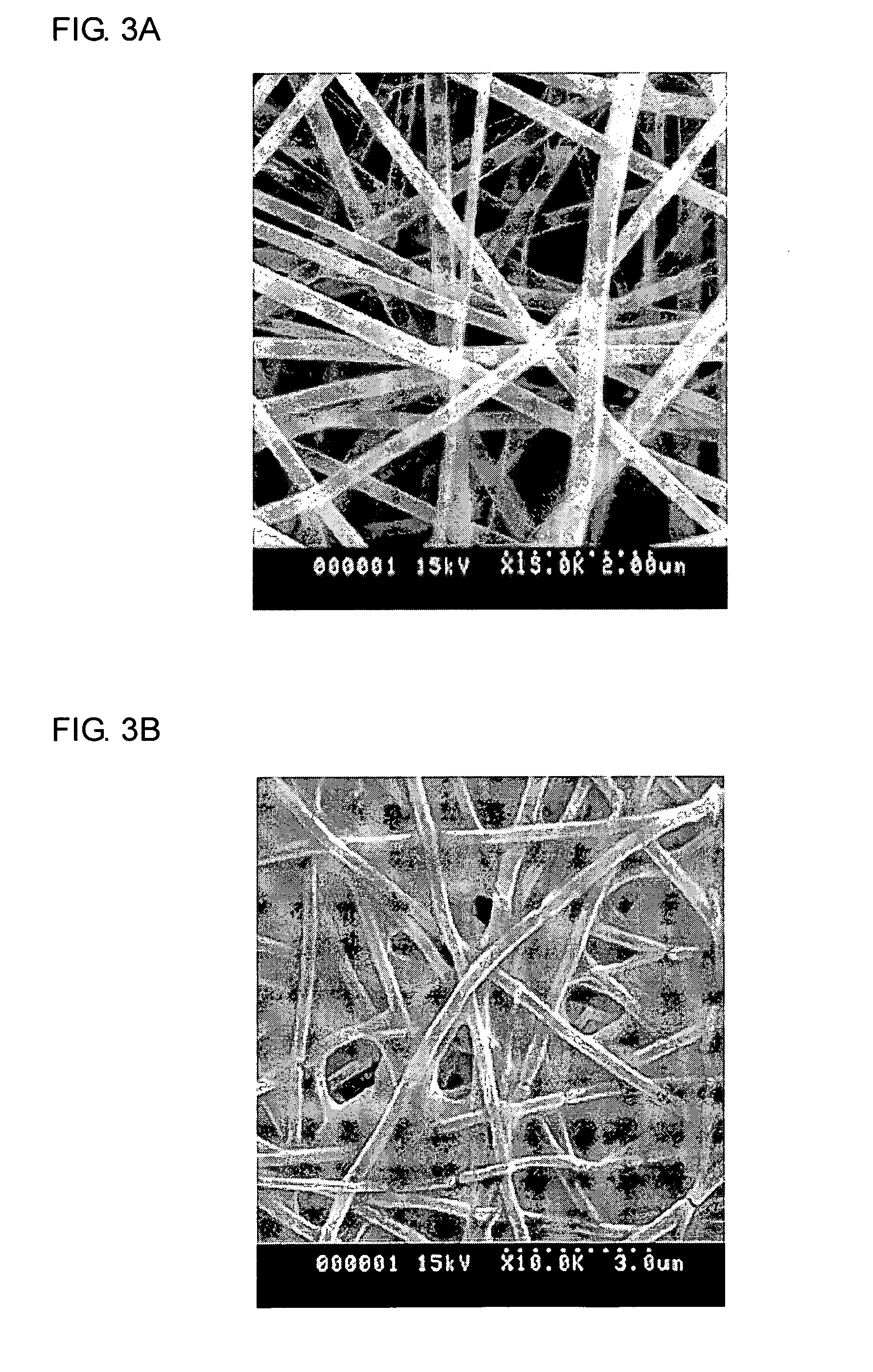
[0061] 6 g of titanium isopropoxide was slowly added in a polymer solution in which 30 g of polyvinylacetate (Mw 500,000, a product of Aldrich Co.) was dissolved in a 270 m of acetone and 30 ml of dimethylformamide mixed solvent. As the reaction was initiated by moisture contained in the solvent, the reaction mixture was changed into a suspension. 2.4 g of acetic acid was then slowly added dropwise as a reaction catalyst to the reaction mixture. As the reaction was proceeding, the suspension was changed into a clear solution. The resulting spinning solution should be spun to ultra-fine titanium dioxide fibers within 24 hours once it was prepared, because if it is left for a long time after the acetic acid was added, the solution is changed into a dark brown color due to hydrolysis of the polymer.

[0062] Electrospinning was performed with the electrospinning apparatus shown in FIG. 2, wherein a FTO-coated transparen...

example 2

Pre-Treatment and Thermal Treatment of the Substrate on Which a Layer of Titanium Dioxide Fibers was Formed Fabricated in Example 1

[0063] The layer of titanium dioxide fibers fabricated in Example 1 includes polymer and titanium dioxide mixed therein. Thus, in order to use the polymer-titanium dioxide composite film-formed substrate as a semiconductor electrode of a dye-sensitized solar cell, the substrate should be thermally treated at a high temperature to remove polyvinylacetate, a polymer binder, and the spun ultra-fine titanium dioxide fibers should be converted into a crystal form. However, if the substrate fabricated in Example 1 is thermally treated at a high temperature without pre-treatment, the titanium dioxide film would not be attached on the FTO-coated substrate but be separated therefrom, and thus, it cannot be used as a semiconductor electrode for a dye-sensitized solar cell.

[0064] Thus, before the thermal treatment, the substrate, on which the polymer-titanium dio...

example 3

Fabrication of a Dye-Sensitized Solar Cell Using the Titanium Dioxide Fiber Layer Fabricated in Example 2

[0072] Dye molecules were adsorbed onto the ultra-fine titanium dioxide fibers in the substrate fabricated in Example 2. Specifically, the transparent conductive glass substrate fabricated in Example 2 was impregnated in 3×10⁻⁴M solution of RuL2(NCS)2 (L=2,2′-bipyridyl-4,4′-dicarboxyl acid) (Ruthenium 535, available from Solaronix,), a ruthenium-based dye, in ethanol for 12 hours, so as to adsorb the dye molecules therein. The resulting substrate was washed with ethanol several times and then dried, thereby to give a semiconductor electrode. Separately, a platinum layer was coated onto a FTO-coated transparent conductive glass substrate to obtain a counter electrode.

[0073] Next, a spacer having a thickness of about 20 μm was located between the semiconductor electrode and the counter electrode fabricated as described above, and a certain pressure was applied thereto at 120° C. ...


PUM


Abstract

A dye-sensitized solar cell comprising a semiconductor electrode comprising electrospun ultra-fine titanium dioxide fibers and fabrication method thereof are disclosed. The dye-sensitized solar cell comprises a semiconductor electrode comprising an electrospun ultra-fine fibrous titanium dioxide layer, a counter electrode and electrolyte interposed therebetween. A non-liquid electrolyte such as polymer gel electrolyte or the like having low fluidity, as well as the liquid electrolyte, can be easily infiltrated thereinto. In addition, electrons can be effectively transferred since titanium dioxide crystals are one-dimensionally arranged.

Description

BACKGROUND OF THE INVENTION [0001] 1. Field of the Invention [0002] The present invention relates to a dye-sensitized solar cell to convert solar energy into electric energy by a photo-electrochemical process and to a fabrication method thereof, and particularly, to a dye-sensitized solar comprising a semiconductor electrode consisting of electrospun ultra-fine titanium dioxide fibers and to a fabrication method thereof. [0003] 2. Description of the Background Art [0004] Since Grätzel's research group in Swiss has reported a dye-sensitized solar cell (B. O'Regan, M. Grätzel, Nature 353, 737 (1991)), researches thereinto have been actively conducted. The dye-sensitized solar cell by Grätzel et al. is a photo-electrochemical solar cell using an oxide semiconductor electrode comprising photosensitive dye molecules that can absorb light within visible region, thereby to generate an electron-hole pair and nano crystalline titanium dioxide that can transfer the generated electron. In this...

Claims


Application Information

Patent Timeline
IPC IPC(8): H01L31/042H01G9/20H01L31/0224H01L31/06H01L51/00H01L51/30H01L51/40
CPCB82Y30/00C01G23/053C01P2002/72C01P2004/03C01P2004/10C09C1/3669Y02E10/549H01G9/2013H01G9/2031H01L51/0086H01L51/4226Y02E10/542H01G9/2009H10K85/344H01G9/20H01L31/04H01L31/0224H01L31/18H10K30/151
Inventor KIM, DONG-YOUNGJO, SEONG-MULEE, WHA-SEOPSONG, MI-YEONKIM, DO-KYUN
Owner KOREA INST OF SCI & TECH
Learn More