
Dual fuel engine control

Inactive Publication Date: 2005-06-09
I SENSE PTY LTD
View PDF7 Cites 110 Cited by
  • Summary
  • Abstract
  • Description
  • Claims
  • Application Information

AI Technical Summary

Benefits of technology

[0032] These data sets may be analyzed, using a variety of tools and methods, including linear programming and simulated annealing, to identify, across the RPM / load range, two derived data sets of diesel and gas fuel flow rates that achieve the optimum dual-fuel economic and environmental outcomes while reducing, maintaining or increasing (as required) the power that the engine would have generated operating on diesel only. Environmental outcomes include maximizing reductions in emissions such as Carbon Dioxide, Oxides of Nitrogen and Particulates, while minimizing any increases in Carbon Monoxide and Hydrocarbons. This is an improvement for both stationary and automotive diesel engines.
[0035] The control system commands the engine's fuel pump or existing electronic engine management system to supply the required diesel flow rate. Simultaneously, the control unit commands the gas flow valve or injector / s to supply the required gas flow rate into the air inlet of the diesel engine. So the optimum amounts of diesel and gas are delivered for the particular conditions of the vehicle and engine at all times. The invention's control system does not replace an existing electronic engine management system but, for example, provides it with a modified signal which maintains or reduces the engine management system command to the diesel injector so that the identified required diesel flow is provided by the injectors. Where the engine has a mechanical fuel control system, the invention's control system intercedes between the throttle and the diesel fuel injection pump to command the identified required modified diesel flow rate. The invention's control system supplies the identified required gas flow by commanding the gas flow valve to vary the cross sectional area of its opening to the programmed setting. If a gas injector or injectors are used, the control system commands a specified variation in the injector / s pulse duration. If the sequential multi-point injection option is selected for gas delivery, the control system varies the timing of operation of the gas injectors so that gas is delivered to the immediate proximity of the air inlet to each cylinder coordinated with the opening of the air inlet port, and the closing of the exhaust outlet port for that cylinder to minimize the amount of gas passing unburned through the cylinders during the scavenging process.
[0040] This is the basis of analyzing engine performance and the basis for improving performance.
[0050] Visualizing software may be used to present the data sets for each parameter as a 3 dimensional surface plotted against load and RPM. The information can also be used to identify ways to improve the driver's control of the vehicle to conserve fuel and reduce unwanted exhaust emissions.

Problems solved by technology

Most prior art systems did not fully assess the consequences to optimised combustion of the operational state and the change of operational state of the vehicle.
Although some switched the gas fumigation off when exhaust temperature or oil pressure exceeded certain predetermined limits they did not consider for example the effect of braking on the emission quality of the exhaust gases.

Method used


Image

  • Dual fuel engine control
  • Dual fuel engine control
  • Dual fuel engine control

Examples


Embodiment Construction

[0051] Preferred embodiments of the invention will be described with reference to the drawings in which

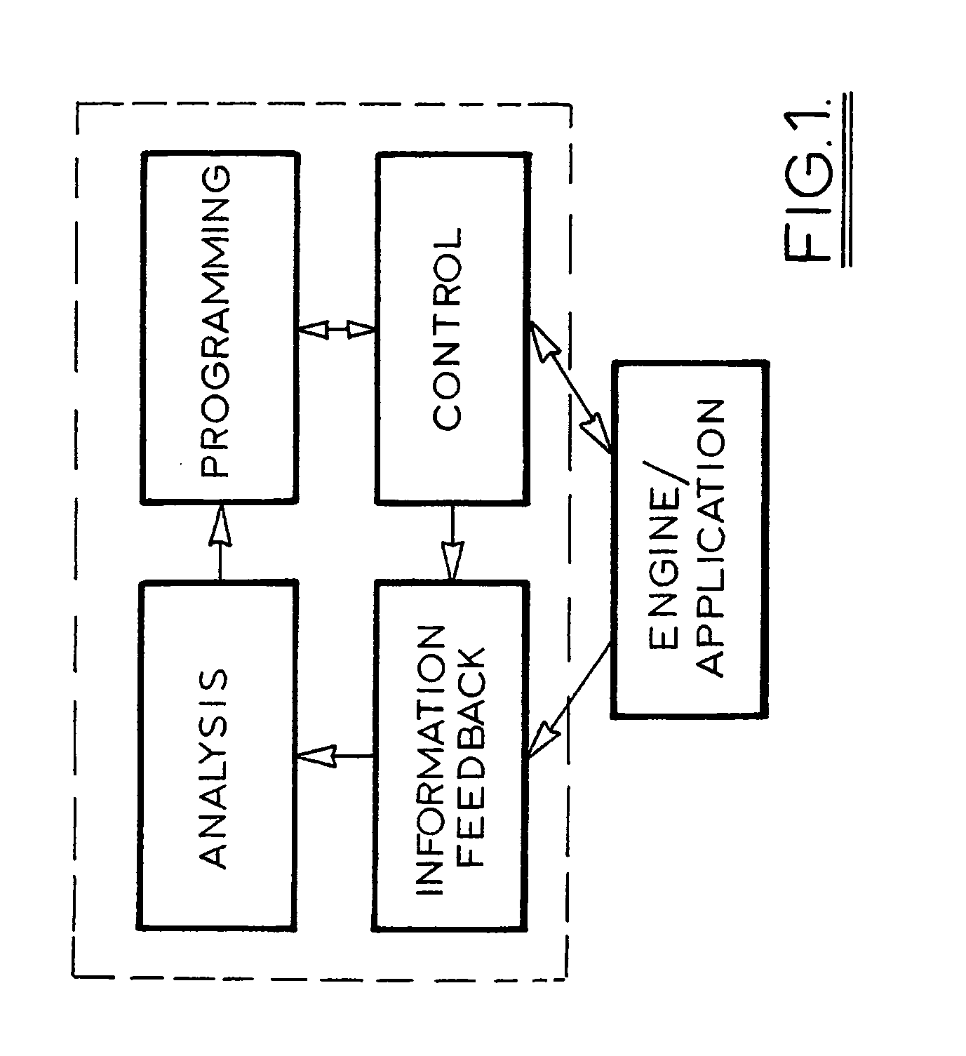
[0052]FIG. 1 is a top level system diagram of the engine fuel management system (EFMS) provided by this invention;

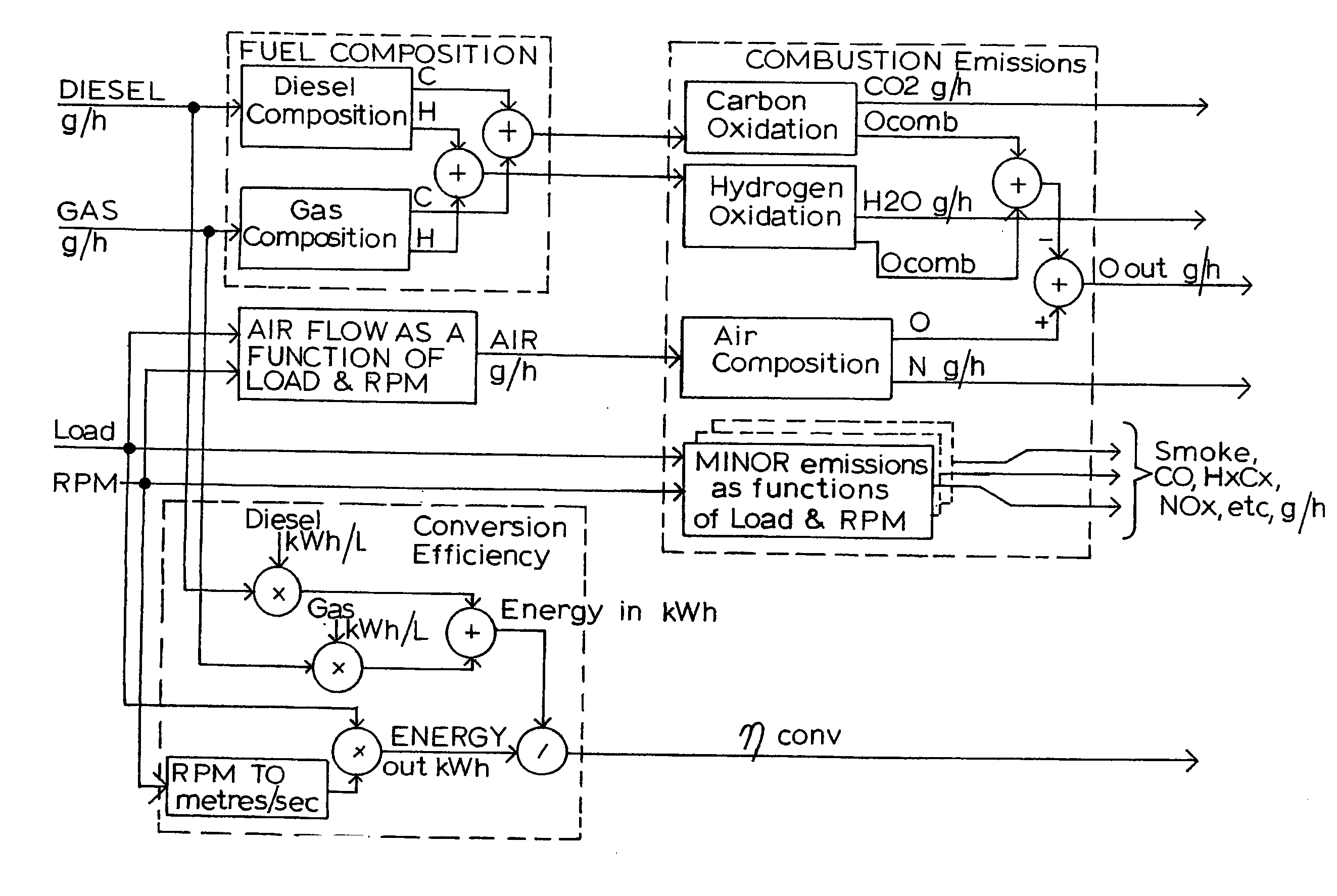
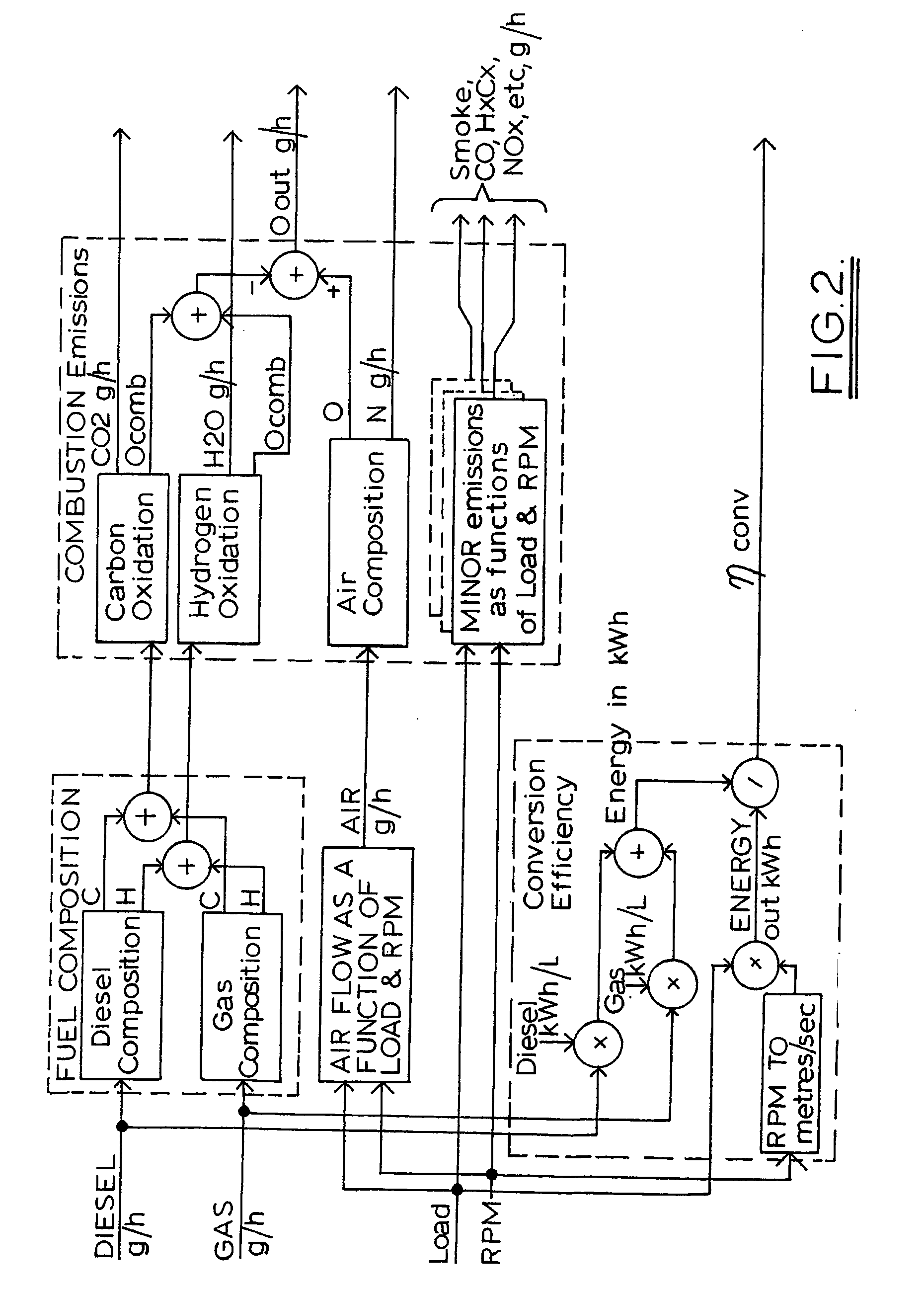
[0053]FIG. 2 is a hybrid model diagram of the system for modeling combustion and deriving emissions and efficiency for all engines and applications;

[0054]FIG. 3 is a system diagram for a gas addition system of this invention for use with a constant engine speed stationary engine;

[0055]FIG. 4 is a system diagram for a gas addition system of this invention for use with a variable engine speed application with a mechanical fuel control / metering system.

[0056]FIG. 5 is a system diagram for a gas addition system of this invention for use with an automotive engine with mechanical fuel control / metering or a basic existing electronic engine management system;

[0057]FIG. 6 is a system diagram for a gas addition system of this invention for use with an automotive engine with ...


PUM


Abstract

A gas substitution system for a dual fuel diesel engine which monitors load and RPM and the operational state of the engine and vehicle including throttle displacement, cruise control, idle, wheel and engine braking, manual control. Data is collected to establish parameters such as fuel consumption and exhaust emissions for load / RPM pair values and using these to create a table of optimum gas substitution values at each load RPM pair within the range of operational states within which substitution is viable. The system is applicable to: constant engine speed stationary applications (gensets); variable engine speed applications, including mobile plant; automative applications with no existing engine management system; automative applications with a basic existing engine management system; automative applications with an advanced existing engine management system.

Description

[0001] This invention relates to the control of fuel supply in a dual fuel engine of the kind where a primary diesel fuel is supplemented with a gas such as natural gas or propane. BACKGROUND TO THE INVENTION [0002] The substitution of part of the diesel fuel with natural gas or liquid propane gas [LPG] results in cost savings and improved emissions through better combustion. U.S. Pat. No. 5,224,457 discloses a dual fuel system for a stationary engine. The engine has a diesel injection system controlled by an electronic control unit and a metering valve and mixer which controls introduction of gas into the air intake for the engine. An electronic governor controls the metering valve and a link controller coordinates the ECU and the governor. [0003] U.S. Pat. No. 5,226,396 addresses the problem of varying fuel types and quality of combustion by measuring the oxygen content of the exhaust gases and adjusting the gas supply to the diesel air intake in response to the oxygen content of ...

Claims


Application Information

Patent Timeline
IPC IPC(8): F02M21/02F02D19/02F02D19/08F02D41/00F02D41/24F02D41/26
CPCF02B2201/06F02D19/0631F02D19/105Y02T10/36F02D41/2422F02D41/26F02D41/0027Y02T10/30F02D41/00F02M21/02
Inventor EDWARDS, JOHN
Owner I SENSE PTY LTD
Learn More