Solar power generation apparatus, solar power generation system, and method of manufacturing solar power generation apparatus

a solar power generation and solar energy technology, applied in the field solar power generation system, and manufacturing method can solve the problems of increasing the price of solar power generation apparatus, time-consuming solar battery module formation, and difficulty in assembling solar cells in series, so as to reduce the influence of partial shade and variation in characteristic, reduce manufacturing cost, and simple structure

Inactive Publication Date: 2005-06-09
CANON KK
View PDF48 Cites 305 Cited by
  • Summary
  • Abstract
  • Description
  • Claims
  • Application Information

AI Technical Summary

Benefits of technology

[0021] It is an object of the present invention to provide a solar power generation apparatus which can reduce the manufacturing cost with a simple structure and also reduce the influence of partial shade and a variation in characteristic.

Problems solved by technology

However, these prior arts have the following problems.
Generally, formation of solar battery modules is time-consuming because it requires a number of processes including a cutting step of dividing a substrate having an electromotive layer formed thereon into solar cells, an end portion etching step of forming non-power-generation regions that insulate the solar cells from each other, a step of sequentially connecting the solar cells in series by using wiring members such as interconnects, a step of connecting a bypass diode to reduce the influence of partial shade, a step of covering the series-connected solar cells, and a step of fitting a frame into the end portion of the covered structure.
In addition, since the members to be used are expensive, the price of solar power generation apparatuses increases.
Especially, when a large solar battery module is to be manufactured, the step of connecting a number of solar cells in series takes a time and labor.
This poses a serious problem in manufacturing a large solar battery module.
Furthermore, since the solar cells are connected in series, the influence of partial shade on the power generation efficiency is also large.
However, even when this method is used, the influence of partial shade on the remaining power generating cells cannot be completely eliminated.
However, a time and labor are still necessary for the cutting step and etching step for the end portion of each solar cell in forming solar cells.
However, this work is difficult and increases the cost.
Hence, when the number of solar cells increases, and the area of the solar battery module becomes large, the loss in current collection considerably increases.
However, if this measure is taken, the weight and volume of the current collection bus bar become very large, resulting in difficulty in manufacture and transportation.

Method used


Image

  • Solar power generation apparatus, solar power generation system, and method of manufacturing solar power generation apparatus
  • Solar power generation apparatus, solar power generation system, and method of manufacturing solar power generation apparatus
  • Solar power generation apparatus, solar power generation system, and method of manufacturing solar power generation apparatus

Examples


first embodiment

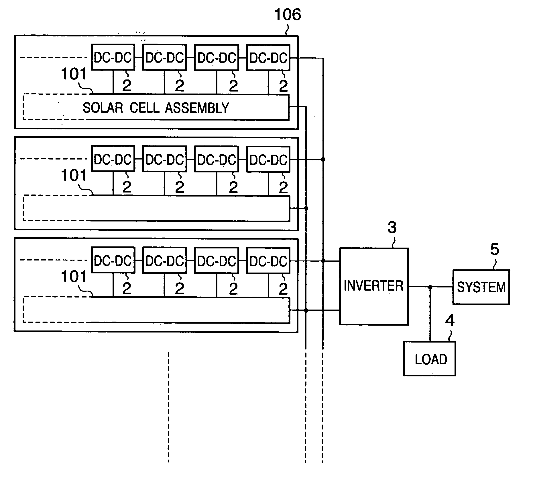
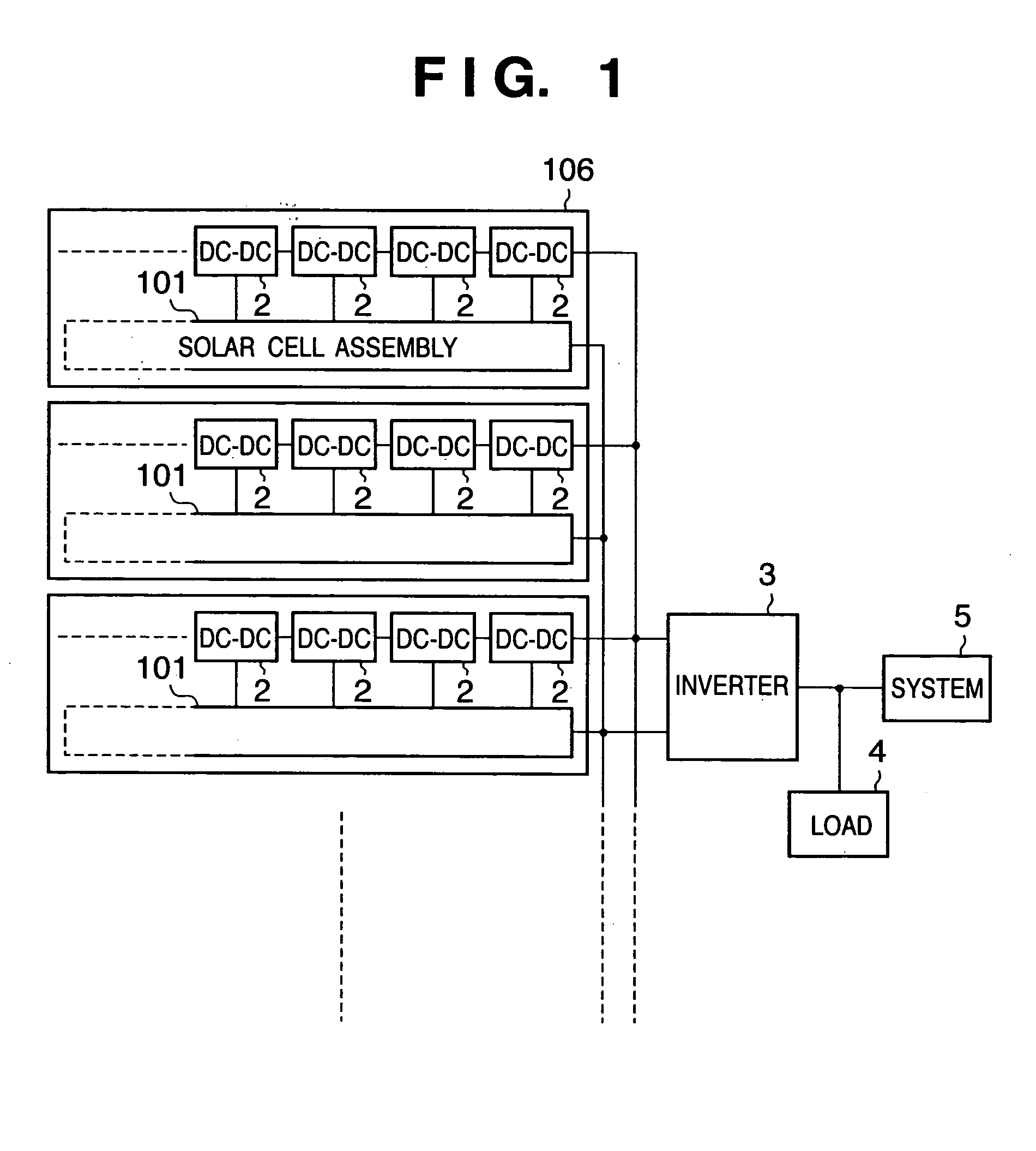
[0069]FIG. 1 is a schematic view showing the arrangement of a solar power generation system according to the first embodiment of the present invention. The solar power generation system comprises solar cell assemblies 101 each constructed by a plurality of solar cells formed on one conductive substrate, DC / DC converters 2, an inverter 3, a load 4, and a system 5.

[0070] In this specification, a solar cell is a structure having a photo voltaic layer divided into a predetermined region. A solar cell is a minimum unit having a function as a solar battery capable of extracting a power from its photovoltaic layer.

[0071] The plurality of solar cells in the solar cell assembly 101 are independent from each other. They are not connected in series. A DC power output from each solar cell is input to a corresponding one of the DC / DC converters 2 that are arranged in a one-to-one correspondence with the solar cells. The DC powers are boosted at a predetermined boost ratio. All the outputs from...

second embodiment

[0186] A solar power generation system according to the second embodiment of the present invention will be described below. A description of the same parts as in the first embodiment will be omitted, and characteristic parts of the second embodiment will mainly be described below.

[0187]FIG. 10 is a schematic view showing the outer appearance of the second embodiment. FIG. 11 is an equivalent circuit diagram of the second embodiment.

[0188] In this embodiment, almost the same solar cell assembly as in the first embodiment is used, and a detailed description thereof will be omitted.

[0189]FIG. 12 is an enlarged view of a connection portion between a DC / DC converter 2 and one of solar cells 22 that constitute the solar cell assembly to which the DC / DC converter used in this embodiment is attached. The attachment position of the DC / DC converter 2 to each solar cell is the same as in the first embodiment except an output terminal 59 extends from the encapsulating portion of the DC / DC co...

third embodiment

[0202] A solar power generation system according to the third embodiment of the present invention will be described below. A description of the same parts as in the first and second embodiments will be omitted, and characteristic parts of the third embodiment will mainly be described below.

[0203] The solar cell used in this embodiment has almost the same structure as that used in the first embodiment except the multilayered structure of the semiconductor layer.

[0204] More specifically, first, as a lower electrode layer, an Al layer containing 1% Si and having a layer thickness of 5,000 Å is formed by sputtering on a cleaned and rolled long 0.1-mm thick stainless substrate as a conductive substrate. Next, an n / i / p amorphous silicon semiconductor layer is formed. For the p-type semiconductor, B2H6, SiH4, and H2 gases are used. For the i-type semiconductor, SiH4 and H2 gases are used. For the n-type semiconductor, PH3, SiH4, and H2 gases are used. A 100-Å thick p-type semiconductor l...


PUM


Abstract

A solar cell assembly including a plurality of solar cells is formed on a common substrate, and a DC/DC converter which converts the output from the solar cell is connected to each solar cell to constitute a solar power generation apparatus. The output from the solar power generation apparatus is converted into an AC power by an inverter and supplied to a load or commercial AC power system. Since the arrangement is simplified, the manufacturing cost can be reduced, and the influence of partial shade or a variation in characteristic decreases.

Description

TECHNICAL FIELD [0001] The present invention relates to a solar power generation apparatus, a solar power generation system, and a method of manufacturing the solar power generation apparatus and, more particularly, to a solar power generation apparatus and solar power generation system, which have a plurality of solar cells formed on a common substrate and a method of manufacturing the solar power generation apparatus. BACKGROUND ART [0002] As problems such as global warming due to emission of CO2 and the like by use of fossil fuel and radioactive contamination due to accidents at nuclear power plants or radioactive waste are becoming increasingly serious in recent years, there has been a growing interest in global environment and energy. Under these circumstances, solar power generation that uses sunlight as an unlimited source of clean energy, geothermal power generation that uses geothermal heat, wind power generation that uses wind power, and the like have been put into practic...

Claims


Application Information

Patent Timeline
Patent Type & Authority Applications(United States)
IPC IPC(8): H01L31/00
CPCH01L31/02021Y02E10/50H02M3/33569Y10S136/293H02M3/33573
Inventor TOYOMURA, FUMITAKATAKEHARA, NOBUYOSHI
Owner CANON KK
Why Eureka
Try Eureka