
Multitube reactor, vapor phase catalytic oxidation method using the multitube reactor, and start up method applied to the multitube reactor

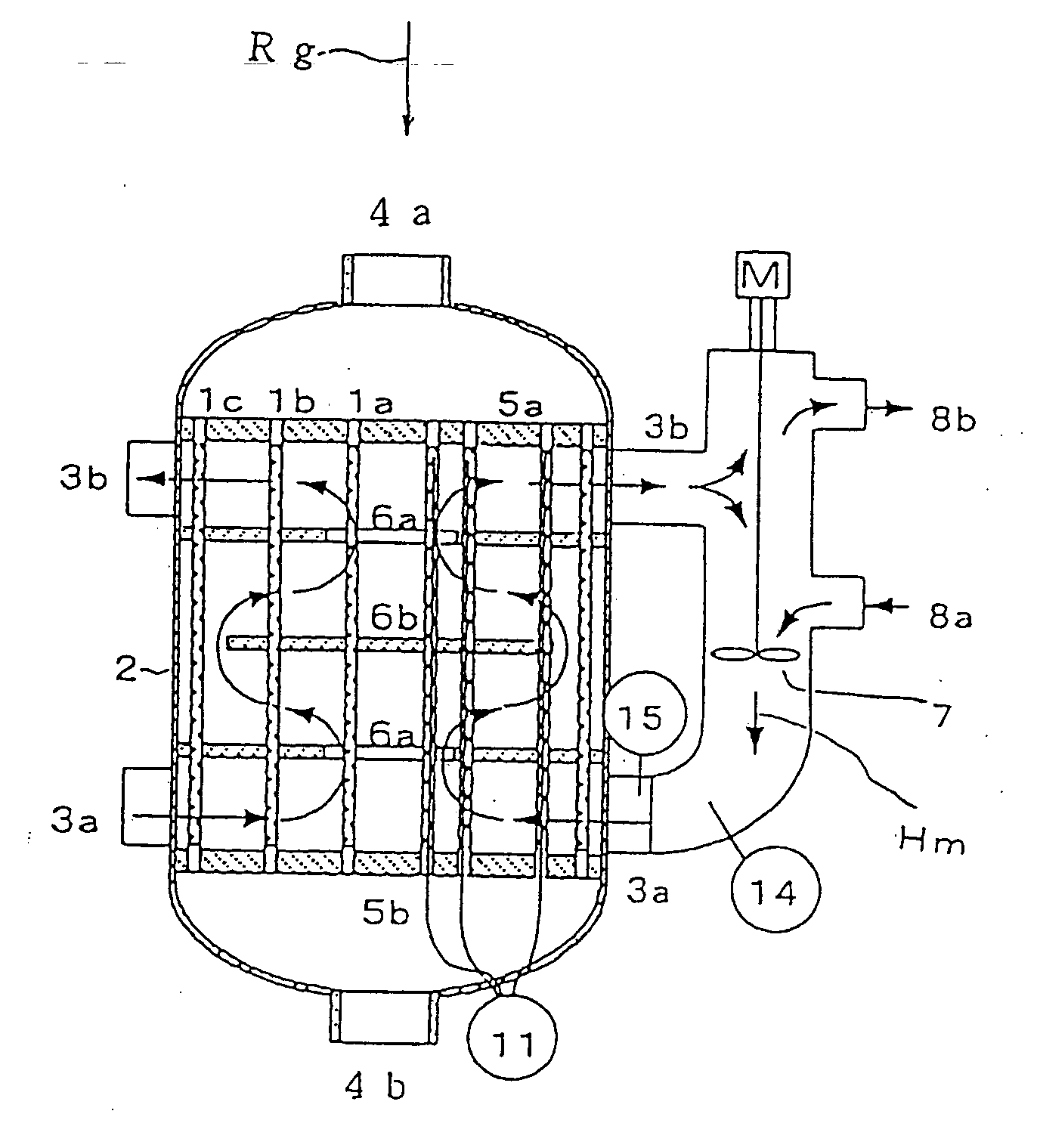
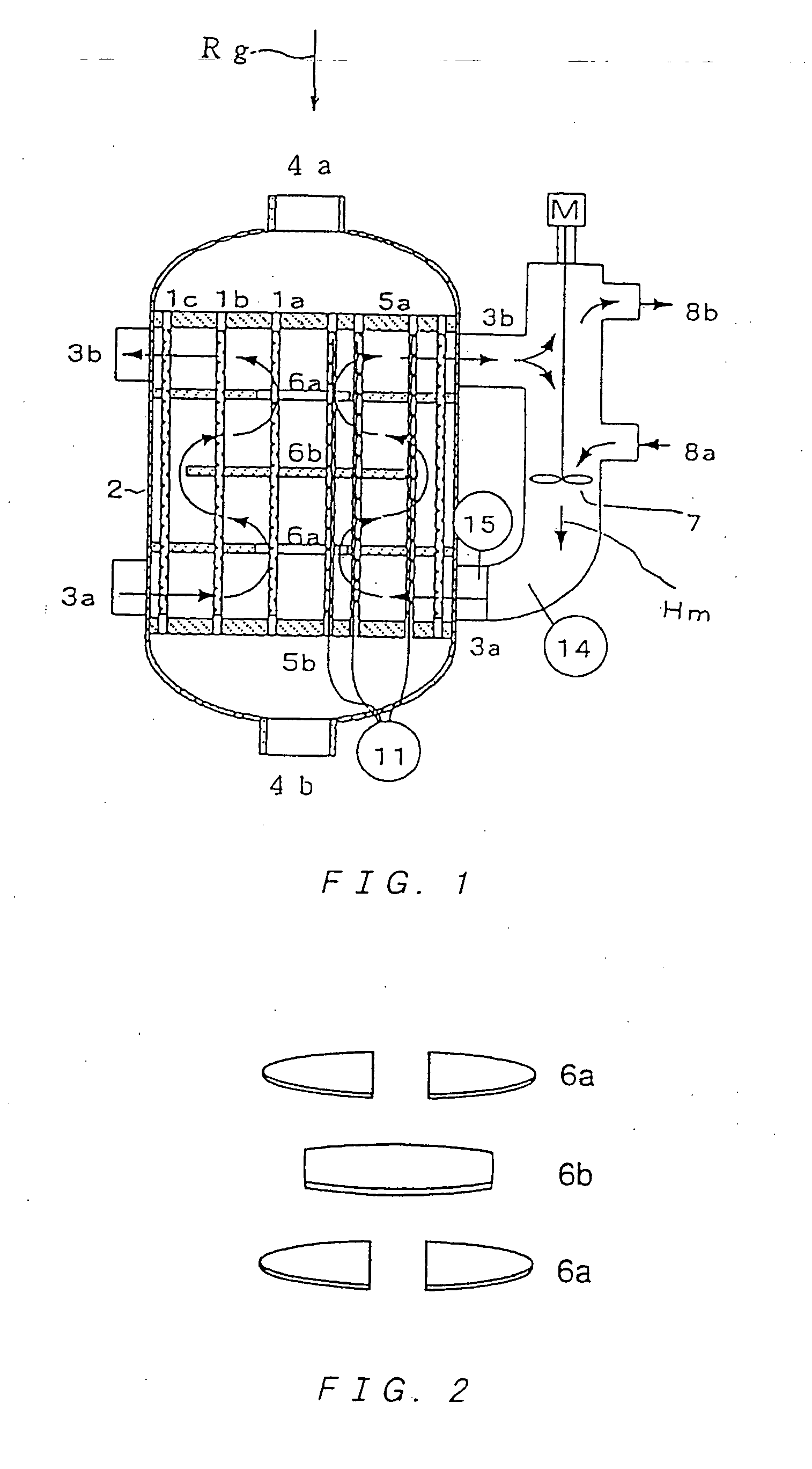
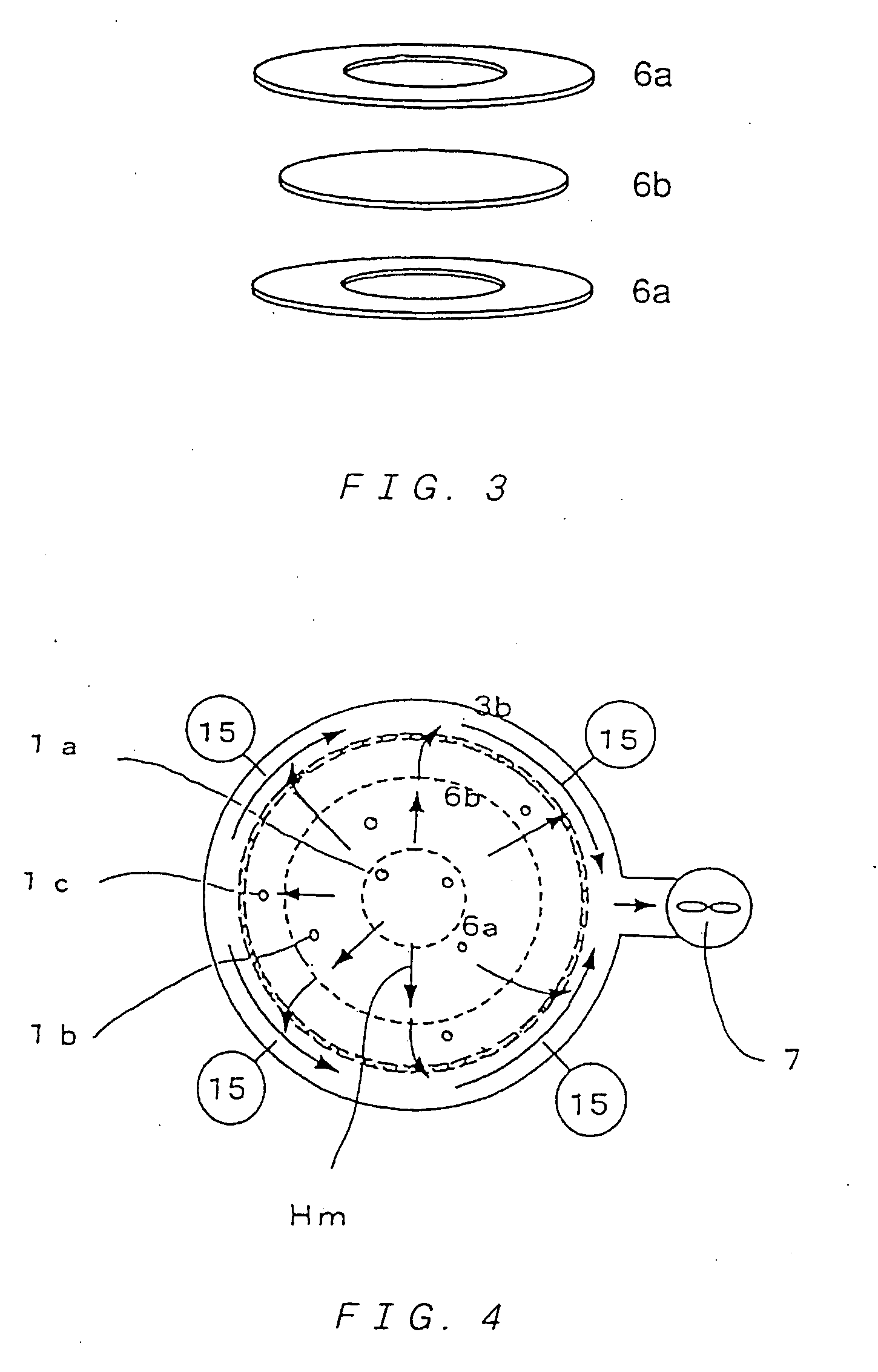
a multi-tube reactor and vapor phase technology, applied in the direction of metal/metal-oxide/metal-hydroxide catalysts, physical/chemical process catalysts, lighting and heating apparatus, etc., can solve the problem of scattering, reduced yield of target products, irregular amount of catalyst inside reaction tubes, etc., to reduce catalyst life, reduce yield, affect catalyst activity and selectivity

Active Publication Date: 2005-06-16
MITSUBISHI CHEM CORP
View PDF13 Cites 13 Cited by
  • Summary
  • Abstract
  • Description
  • Claims
  • Application Information

AI Technical Summary

Benefits of technology

"The present invention provides a multitube reactor and a vapor phase catalytic oxidation method that can improve the life of a catalyst and prevent yield reduction of a target product. The reactor has a shell equipped with reaction tubes inside which a heat medium flows outside. The reaction tubes are selected from tubes having the same nominal outside diameter and same nominal wall-thickness tolerances. The method includes circulating the heat medium through the outside of the reaction tubes and feeding a reaction raw material gas inside the reaction tubes packed with a catalyst to obtain a reaction product gas. The method can effectively prevent hot spots formation, clogging of reaction tubes, and reduce the temperature at the product discharging port of the reactor. The present invention also provides a vapor phase catalytic oxidation method using a fixed bed multitube heat-exchanger type reactor with a plurality of reaction tubes and baffles connected to the reaction tubes through connecting sites for changing a flow path of a heat medium. The method includes setting catalyst packing specifications in the reaction tubes so that catalyst layer peak temperature sites are not located at the connecting sites between the baffles and the reaction tubes. The method can also include using a multitube reactor with different catalyst packing specifications in the reaction tubes. The present invention provides a solution for improving the performance of a vapor phase catalytic oxidation reactor and preventing issues such as yield reduction and clogging of reaction tubes."

Problems solved by technology

When differences of inner volumes among the plurality of reaction tubes equipped inside the shell is large, amounts of the catalyst packed inside the reaction tubes are irregular and a scatter arises.
As a result, a flow rate of the raw material gas fed or a retention time differs among the reaction tubes, thereby becoming a factor causing yield reduction of a target product and reduced catalyst life.
Further, a localized abnormal high-temperature site (hot spot) may form in the reaction tubes provoking a reaction out of control, thereby causing a problem of inhibiting a continuous operation.
A reactor in which outer walls of the reaction tubes and the baffle are not fixed also exists, but the amount of the heat medium flowing through this clearance is limited.
There is a state of poor heat removal in the reaction tubes in a portion where flow of the heat medium is insufficient inside the shell.
A localized abnormal high-temperature zone (hot spot) may form in the reaction tubes which are in a state of poor heat removal, possibly resulting in a reaction out of control.
Further, a reaction may not become out of control, but problems arise including ease of clogging the reaction tubes, yield reduction of the reaction product gas, deterioration of the catalyst life, and inhibition of a stable operation for a long period of time.
Thus, the method has a fault that high concentration of a product (meth)acrolein easily causes an autooxidation reaction (autolysis reaction).
Thus, high temperature at a process outlet causes autooxidation at the reactor outlet easily.
The autooxidation reaction results in problems of a combustion reaction of the product, equipment breakdown due to temperature increase, and yield reduction.
Thus, an amount of heat removal becomes large and a cooling portion (cooling zone and heat exchanger) enlarges, thereby becoming disadvantageous in point of cost.
Further, even if a significant autooxidation reaction is not caused, an autooxidation reaction is caused by a part of a product, which arises a problem of yield reduction of a target product as a whole.
However, a large volume of a high temperature gas is introduced to the reaction tubes according to the above-mentioned method, thereby changing an oxidation state of the catalyst.
Therefore, catalytic activity and selectivity may be affected, possibly resulting in yield reduction or reduced catalyst life.

Method used


Image

  • Multitube reactor, vapor phase catalytic oxidation method using the multitube reactor, and start up method applied to the multitube reactor
  • Multitube reactor, vapor phase catalytic oxidation method using the multitube reactor, and start up method applied to the multitube reactor
  • Multitube reactor, vapor phase catalytic oxidation method using the multitube reactor, and start up method applied to the multitube reactor

Examples


example 1

[0268] For an oxidation reaction of propylene, catalyst powder having a composition (atomic ratio) of Mo(12)Bi(5)Ni(3)Co(2)Fe(0.4)Na(0.2)B(0.4)K(0.1)Si(24)O(x) was produced (oxygen composition x is a value determined from oxidation states of the respective metals) as a former stage catalyst.

[0269] The catalyst powder was molded in to ring-shaped catalysts having an outer diameter of 5 mmφ, an inner diameter of 2 mmφ, and a height of 4 mm.

[0270] Two stainless steel tubes both having a length of 3,500 mm, and respectively having an outside diameter of 30.57 mmφ, a wall-thickness of 1.80 mm, and an outside diameter of 30.23 mmφ, a wall-thickness of 2.10 mm were used as reaction tubes (nominal outside diameter of 30.40 mmφ and nominal wall-thickness of 1.80 mm). Note that, an outside diameter tolerance and a wall-thickness tolerance of the tubes are ±0.17 mm (±0.56%) and +0.30 mm, −0 mm (+16.7%, −0%), respectively.

[0271] Further, a reactor used had a shell inner diameter of 100 mmφ. ...

example 2

[0278] Two stainless steel tubes both having a length of 3,500 mm, and respectively having an outside diameter of 30.58 mmφ, a wall-thickness of 1.80 mm, and an outside diameter of 30.22 mmφ, a wall-thickness of 2.14 mm were used as the reaction tubes (nominal outside diameter of 30.40 mmφ and nominal wall-thickness of 1.80 mm). Note that, the outside diameter tolerance and the wall-thickness tolerance of the tubes are ±0.18 mm (±0.59%) and +0.34 mm, −0 mm (+18.9%, −0%), respectively.

[0279] The reaction was conducted in the same manner as in Example 1 except for the reaction tubes.

[0280] The reaction was conducted for 1 week at a heat medium Hm temperature of 330° C. The propylene conversion and the yield were 97.2% and 90.0%, respectively, and the highest temperature of the reaction catalyst layers was 394° C.

[0281] The reaction was continued for 1 month maintaining the heat medium Hm temperature at 330° C. The propylene conversion and the yield were 96.8% and 89.7%, respectivel...

example 3

[0282] Two stainless steel tubes both having a length of 3,500 mm, and respectively having an outside diameter of 30.65 mm®, a wall-thickness of 1.80 mm, and an outside diameter of 30.15 mm®, a wall-thickness of 2.16 mm were used as the reaction tubes (nominal outside diameter of 30.40 mmφ and nominal wall-thickness of 1.80 mm). Note that, the outside diameter tolerance and the wall-thickness tolerance of the tubes are ±0.25 mm (±0.82%) and +0.36 mm, −0 mm (+20%, −0%), respectively.

[0283] The reaction was conducted in the same manner as in Example 1 except for the reaction tubes.

[0284] The reaction was conducted for 1 week at a heat medium Hm temperature of 330° C. The propylene conversion and the yield were 97.4% and 89.9%, respectively, and the highest temperature of the reaction catalyst layers was 429° C.

[0285] The reaction was continued for 1 month maintaining the heat medium Hm temperature at 330° C. The propylene conversion and the yield were 94.0% and 88.0%, respectively,...


PUM

PropertyMeasurementUnit
temperatureaaaaaaaaaa

Abstract

A multitube reactor, wherein tubes having smaller tolerance between a nominal size and actual sizes are used as reaction tubes to stably perform a high yield reaction for a long period, a catalyst is filled into the reaction tubes so that the catalyst layer peak temperature portions of the reaction tubes are not overlapped with the connection sites thereof with baffles to effectively prevent hot spots from occurring and stably perform a reaction for a long period without the clogging of the reaction tubes, a heat medium and raw material gas are allowed to flow in the direction of a countercurrent and a specified type of catalyst is filled into the reaction tubes so that activity is increased from the inlet of the raw material gas to the outlet thereof to prevent the autooxidation of products so as to prevent equipment from being damaged due to the reaction, and, at the time of starting, gas with a temperature of 100 to 400° C. is led to the outside of the reaction tubes to increase the temperature of the reaction tubes and, a heat medium, which is solid at the room temperature, is heated to circulate to the outside of the reaction tubes to efficiently start up the reactor without affecting the activity of the catalyst.

Description

TECHNICAL FIELD [0001] The present invention relates to a multitube reactor applied to a method of producing (meth)acrolein and / or (meth)acrylic acid by oxidizing propylene, propane, isobutylene, isobutanol, or t-butanol with a molecular oxygen-containing gas, a vapor phase catalytic oxidation method using the multitube reactor, and to a start up method applied to the multitube reactor. BACKGROUND ART [0002] A conventional multitube reactor is equipped with a plurality of reaction tubes having a catalyst packed therein and a plurality of baffles inside a shell for feeding and circulating inside the shell a fluid for heat removal (hereinafter, referred to as “heat medium”) introduced into the shell. A raw material gas fed inside the reaction tubes reacts in the presence of the catalyst inside the reaction tubes, to thereby generate heat of reaction. The heat of reaction is removed by a heat medium circulating inside the shell. [0003] When differences of inner volumes among the plural...

Claims


Application Information

Patent Timeline
Patent Type & Authority Applications(United States)
IPC IPC(8): B01J8/06C07C45/33C07C45/35C07C51/215C07C51/25
CPCB01J8/06F28F2265/10B01J23/002B01J23/8876B01J35/026B01J2208/00221B01J2208/0053B01J2208/00716B01J2523/00C07C45/33C07C45/35C07C51/215C07C51/252F28D7/1607F28D2021/0022F28F9/026F28F9/028F28F9/22B01J8/067C07C47/22C07C57/04B01J2523/12B01J2523/13B01J2523/22B01J2523/305B01J2523/41B01J2523/54B01J2523/68B01J2523/842B01J2523/845B01J2523/847B01J35/50B01J35/55
Inventor YADA, SHUHEIHOSAKA, HIROCHIKAGORIKI, MASAYASUJINNO, KIMIKATSUOGAWA, YASUSHISUZUKI, YOSHIRO
Owner MITSUBISHI CHEM CORP
Learn More