Power cogeneration system and apparatus means for improved high thermal efficiencies and ultra-low emissions

a power cogeneration system and ultra-low emission technology, applied in the direction of machines/engines, jet propulsion plants, hot gas positive displacement engine plants, etc., can solve the problems of reducing the thermal efficiency of power cogeneration methods. , to achieve the effect of increasing the thermal efficiency of power cogeneration method system and apparatus

Inactive Publication Date: 2005-06-23
AES DEV CO
View PDF15 Cites 55 Cited by
  • Summary
  • Abstract
  • Description
  • Claims
  • Application Information

AI Technical Summary

Benefits of technology

[0013] To achieve both power turbine engine ultra-low NO.sub.x and CO exhaust emissions (as well as reduced “greenhouse gas” carbon dioxide (CO.sub.2) emissions and enhanced simple-cycle operating thermal efficiencies, the inventor's AES gas turbine power cycle system and apparatus is described in U.S. Pat. No. 6,532,745 dated Mar. 18, 2003. The cited invention's further described partially-open gas turbine cycle contains multiple heat recovery devices for transferring waste heat to varied process gases and steam resulting in a cogeneration facility overall maximum thermal efficiency that “may approach 100%”.
[0014] The present invention describes selected process elements from the cited partially-open AES turbine power cycle and apparatus devices that can be incorporated within a simplified and improved power cogeneration system method having simplified apparatus means that can further achieve increased power cogeneration method system and apparatus thermal efficiencies which may exceed 115%.
[0015] The addition of these selected apparatus assembly device alternatives to the presented power cogeneration method employing a power engine unit of the example gas turbine engine type, as later further described and shown in FIG. 2, may increase the presented power cogeneration system's method overall thermal efficiency to greater than 115%.

Problems solved by technology

Due to the high temperatures and speed of completed fuel combustion, the scientific community has been unable to reach a consensus as to precisely what series of altered chemical reactions occur when water vapor and / or carbon dioxide is introduced into an engine's fuel combustion chamber assembly or subassembly device.
Both the present air separation art methods' high production energy costs of producing acceptable combustion grade oxygen, and the lack of devised combustion system methods to control preset desired oxy-fuel combustion burner or combustion chamber assembly or subassembly uniform maximum temperatures, have collectively curtailed oxy-fuel combustion applications within present fuel thermal energy to power energy conversion facilities.
The majority of Brayton simple open-cycle aero-derivative-style Low-NO.sub.x art gas turbine engines are predominantly presently limited in achieving shaft output horsepower rating with 26% to 39% thermal efficiencies, whereas most simple cycle industrial-style Low-NO.sub.x art gas turbine engines are predominantly presently limited in achieving shaft output horsepower rating with 27% to 34% engine thermal efficiencies.
The best available applied turbine engine and reciprocating-type engine low NO.sub.x combustion technology for limiting NO.sub.x emissions, using near-stiochiometric air / fuel primary combustion reaction chemistry means, still results in the production of NO.sub.x and CO that are no longer acceptable for new power or energy conversion facilities in numerous states and metropolitan environmental compliance jurisdictions.

Method used


Image

  • Power cogeneration system and apparatus means for improved high thermal efficiencies and ultra-low emissions
  • Power cogeneration system and apparatus means for improved high thermal efficiencies and ultra-low emissions
  • Power cogeneration system and apparatus means for improved high thermal efficiencies and ultra-low emissions

Examples


Embodiment Construction

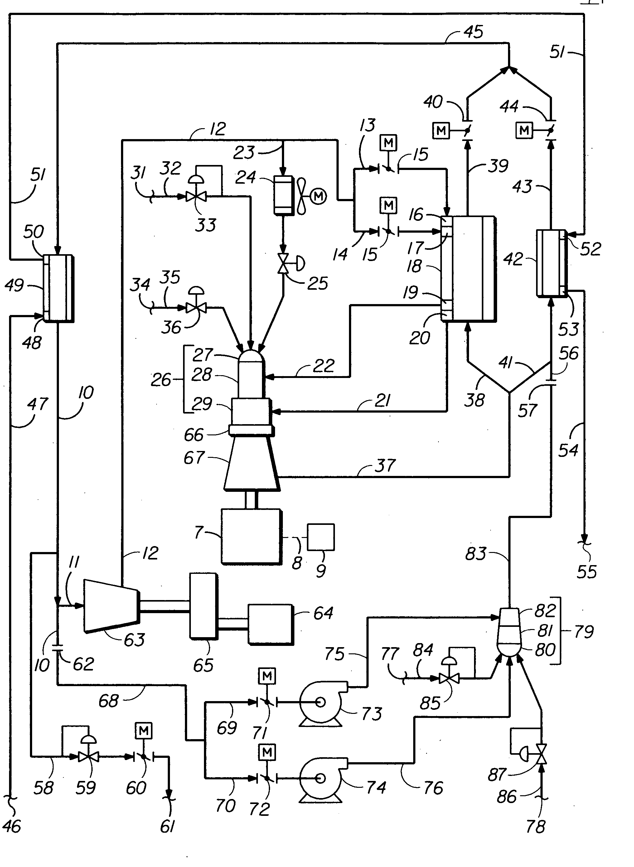
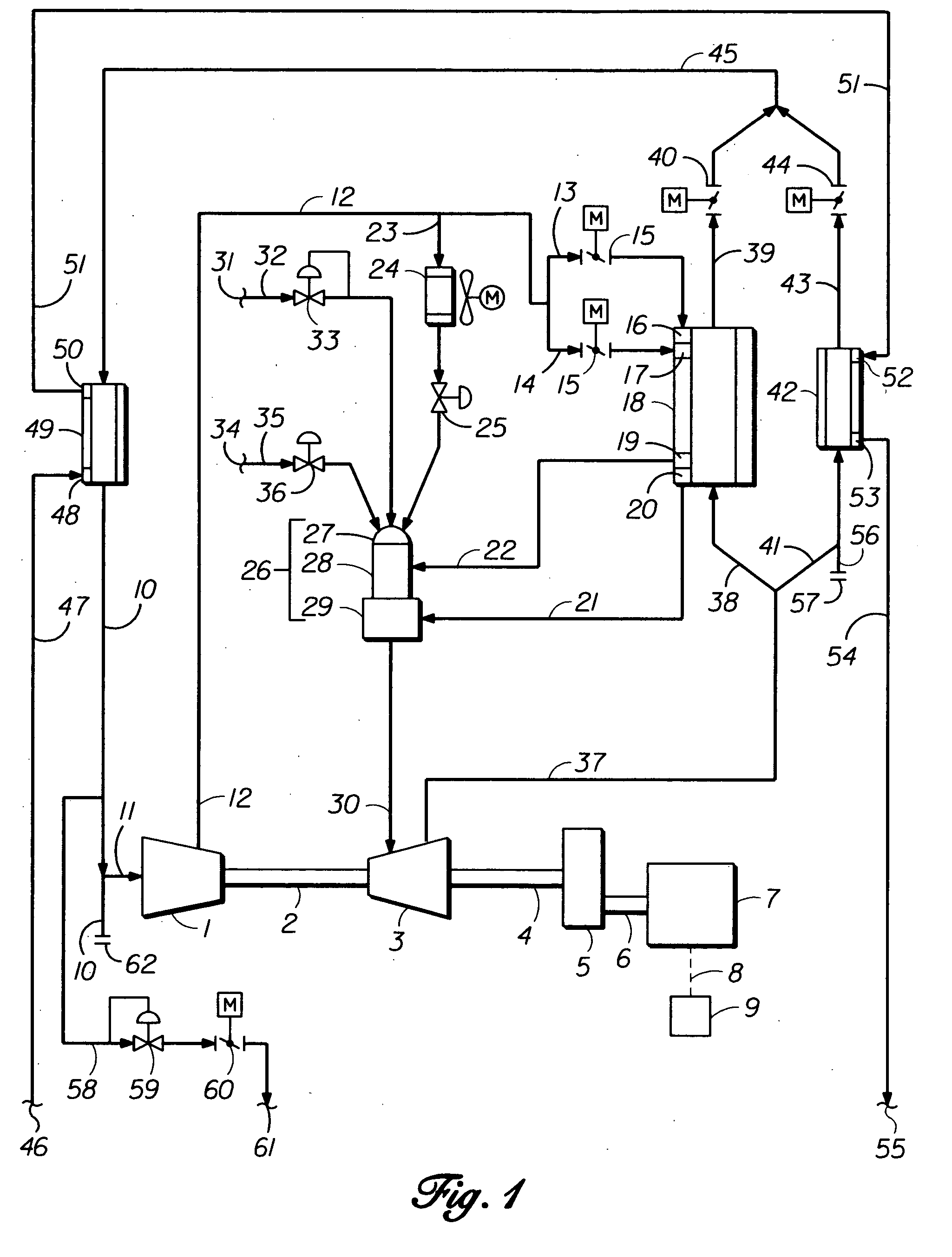
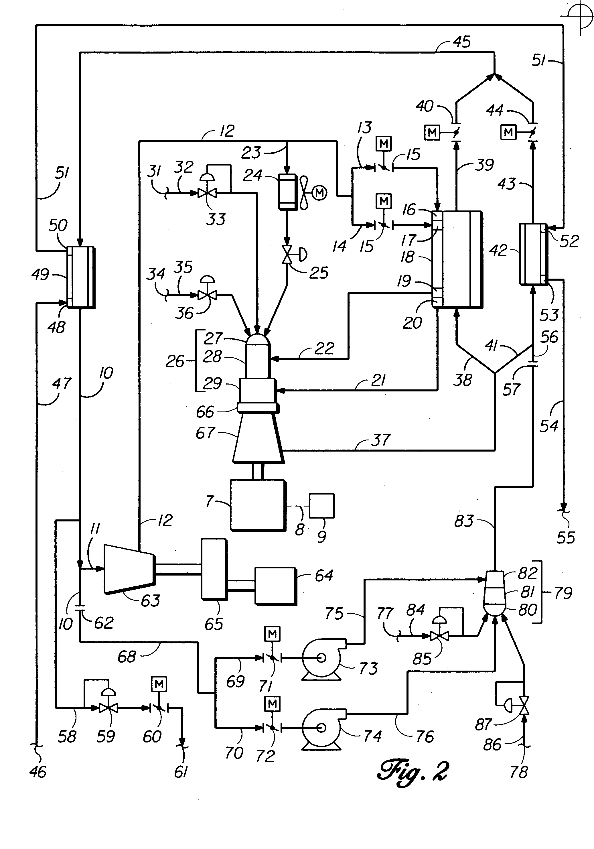
[0082] Referring now more particularly to FIG. 1, an example modified conventional gas turbine engine power unit's exhaust recycle gas compressor section 1 comprises two or more recycle exhaust gas compression stages, positioned in series, with a final stage of radially directed discharge flow of compressed or re-pressurized recycle exhaust gas. In the case of a two-shaft turbine engine, the power to drive the recycle gas compressor section 1 is transmitted by shaft 2, on which one or more high-pressure power extraction turbine stages are mounted within the combustion hot gas expansion power turbine assembly 3. The second shaft, designed for mechanical equipment or generator drive applications, has one or more low-pressure hot gas expansion power stages mounted on power output shaft 4, with coupling means for power transmission to rotate the driven equipment.

[0083] The invention's improved power cogeneration method adaptation to modified conventional gas turbine engine driven mecha...


PUM


Abstract

A power cogeneration system employing a partially-open gaseous fluid cycle method and apparatus devices for oxy-fuel combustion conversion of a given hydrocarbon composition fuel's heat-value energy into mechanical or electrical power energy, and transferred useful heat energy, with accompanying large reductions of consumed fuel and undesirable exhaust emissions.

Description

BACKGROUND OF THE INVENTION [0001] To achieve a goal of significantly reducing a power cogeneration system's emission mass flow rate of the “greenhouse gas” (carbon dioxide) by a given percentage amount, it is necessary to proportionally increase the thermal efficiency of a power unit apparatus' conversion of fuel energy to developed mechanical power and useful applied residual thermal energy which therein proportionally reduces the amount of combusted hydrocarbon fuel required to provide the described energy conversion. [0002] It has been well known and practiced for decades that higher humidity air and injected water or steam commingled with conventional air combustion gases increases combustion flame speeds and fuel combustion thermal efficiencies within gas turbine type engines, reciprocating type engines, and other fuel combustion burner apparatus using air / fuel combustion. It has also been well known and practiced that partially re-circulating combustion flue stack gases conta...

Claims


Application Information

Patent Timeline
Patent Type & Authority Applications(United States)
IPC IPC(8): F02C6/04
CPCY02E20/14F02C6/04
Inventor NEARY, DAVID
Owner AES DEV CO
Why Eureka
Try Eureka