Mixed-mode (current-voltage) audio amplifier

a current-voltage, mixed-mode technology, applied in the direction of amplifier combinations, low-frequency amplifiers, electrical transducers, etc., can solve the problems of less uniform coil movement and sound wave distortion, further nonlinearity, and limited uniform static magnetic field size, so as to reduce voltage and current distortion, reduce current distortion, and more even output sound response

Active Publication Date: 2005-06-23
TYMPHANY HK
View PDF13 Cites 63 Cited by
  • Summary
  • Abstract
  • Description
  • Claims
  • Application Information

AI Technical Summary

Benefits of technology

[0028] U.S. Pat. No. 4,393,353 issued Minagawa describes an amplifier that has both a voltage and current feedback circuits in an attempt to reduce both the voltage and current distortion that would be produced by a Class A / B power amplifier stage were feedback not to be used. This scheme is predominantly a voltage feedback system except at the resonance frequency Minagawa provides current feedback in an attempt to match the impedance of the amplifier with the impedance of the driver load at the mechanical resonance peak. This is reported to have two main advantages, first to reduce current distortion and second to obtain a more even output sound response at the mechanical resonance frequency. Although in theory the output impedance of Minagawa's amplifier appears to vary as a function of frequency, and is an improvement over the variable impedance amplifier 300, the output impedance of Minagawa's amplifier only varies in a fairly narrow range of the resonance frequency of the connected driver. It appears that Minagawa attempts to reduce what is referred to as current distortion at only the resonance frequency, which also has the added effect of increasing the output of the amplifier at the resonance frequency. When describing current distortion, therefore, Minagawa appears to focus on that distortion produced by his power amplification stage, ignoring driver distortion due to nonlinearities inherent to the driver such as the nonlinearity of BEMF, and the nonlinearity of the inductance as a function of driver displacement.
[0029] Accordingly, what is needed is an improved audio amplifier that is capable of reducing driver distortion arising from the nonlinearities inherent to the driver. The present invention addresses such a need.
[0030] The present invention provides a mixed-mode (both current- and -voltage-source) audio amplifier. The mixed-mode amplifier includes a voltage sensing feedback path, and a current sensing feedback path to achieve this operation. According to the method and system disclosed herein, the first and second networks vary an effective output impedance of the amplifier as a function of frequency of the input voltage signal, such that at a first frequency range, the amplifier operates substantially as a current amplifier, and at a second frequency range, the amplifier operates substantially as a voltage amplifier, thereby inheriting, among other things, the distortion reduction of the current amplifier the stability of the voltage amplifier. In a preferred embodiment, the first frequency range comprises audible frequencies.
[0031] According to the method and system disclosed herein, the mixed-mode audio amplifier of the present invention effectively reduces nonlinearities that arise at audio frequencies from the use of a low-impedance voltage amplifier only, such as 1) the nonlinearity of the BEMF, 2) nonlinear induction, and 3) the slow drift in resistance of the driver due to temperature changes. By making the output of a current-voltage amplifier have high impedance at audible signal frequencies where these nonlinearities present themselves, the current-voltage audio amplifier of the present invention significantly reduces such nonlinearities and parameter drifts.

Problems solved by technology

There are a number of causes of audio distortion that involve the structure and operation of the voice coil transducer 300.
Nonlinearities in the motor factor in a voice coil transducer result from the fact that the coil and the region of uniform static magnetic field are limited in size, coupled with the fact that the coil moves relative to the static field.
The actual size of the static magnetic field region, and its size relative to the voice coil, represents engineering and economic compromises.
As the audio signal increases in magnitude, the coil tends to move away from the region of maximal static magnetic field, and the motor factor decreases—thus effecting a less uniform coil movement and distorting the sound wave.
Further nonlinearities arise due to other electrodynamical effects caused by the application of the audio signal to the transducer voice-coil.
However, the resulting coil current varies both out of phase and nonlinearly with this voltage.
The spring stiffness of the coil / diaphragm assembly likewise depends on coil position, as does the motor factor—resulting in well-recognized sources of nonlinearity.
Additionally, more gradual changes of coil impedance due to Ohmic and environmental heating cause the drive-current response to drift over time, which causes the effective acoustic gain of a voltage amplifier / driver system to drift as well.
All these effects cause power and frequency dependent distortions of the audio signal.
In summary, voice coil drivers driven by voltage amplifiers in the audio range are susceptible to two main sources of nonlinearities.
One primary reason may be that amplifiers and loudspeaker drivers are not typically designed and built-in an integrated and optimal fashion.
In addition, the inductance of a given driver, which depends on frequency, tends to raise the gain of current amplifiers at high-frequencies, thus jeopardizing their correct operation.
In contrast, current amplifiers have the advantage of reducing distortion, but being less stable and robust at high frequencies.
There are several problems with this approach.
One problem is that it was based on the assumption that the driver load 306 has fixed impedance, which is not the case.
If one designs a variable impedance amplifier 300 based on nominal impedance, then it is clear that there is improper modeling of the electrical dynamics of the driver (assuming any modeling is done at all) and the results will be less than satisfactory.
Another problem with the design of the variable impedance amplifier 300 is that because the voltage and current sensing feedback paths 308 and 322 are resistive, the output impedance of the amplifier 300 remains relatively constant for all input frequencies.

Method used


Image

  • Mixed-mode (current-voltage) audio amplifier
  • Mixed-mode (current-voltage) audio amplifier
  • Mixed-mode (current-voltage) audio amplifier

Examples


Embodiment Construction

[0047] The present invention relates to audio amplifier design. The following description is presented to enable one of ordinary skill in the art to make and use the invention and is provided in the context of a patent application and its requirements. Various modifications to the preferred embodiments and the generic principles and features described herein will be readily apparent to those skilled in the art. Thus, the present invention is not intended to be limited to the embodiments shown, but is to be accorded the widest scope consistent with the principles and features described herein.

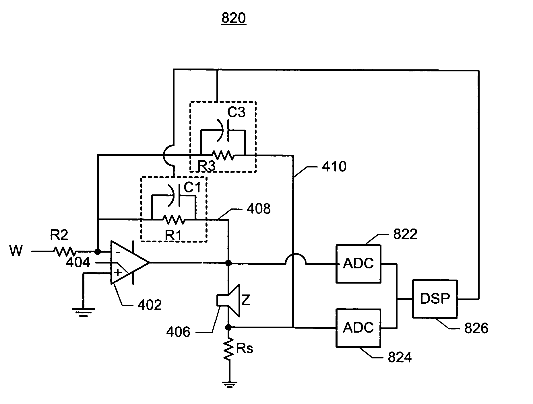
[0048] This present invention provides a mixed-mode (current-voltage) audio amplifier for use that has an effective output impedance that varies as a function of input frequency from nearly zero ohms to thousands of ohms. At certain frequencies, the mixed-mode amplifier may operate with high impedance, thereby acting substantially as a current amplifier, and at other frequencies, it may operate...


PUM


Abstract

A method and system for providing a mixed-mode (current- and voltage-source) audio amplifier is disclosed. The mixed-mode amplifier includes a voltage sensing feedback path including a first network comprising at least one circuit; and a current sensing feedback path including a second network comprising at least one circuit. According to the method and system disclosed herein, the first and second networks vary an output impedance or transconductance of the amplifier as a function of frequency of the input voltage signal, such that at a first frequency range, the amplifier operates substantially as a current amplifier, and at a second frequency range, the amplifier operates substantially as a voltage amplifier, thereby inheriting distortion reduction of the current amplifier and stability of the voltage amplifier.

Description

FIELD OF THE INVENTION [0001] The present invention relates to audio amplifiers and more particularly to a mixed-mode (current-voltage) audio amplifier for reducing nonlinear distortion of an electrodynamic driver. BACKGROUND OF THE INVENTION [0002] Audio reproduction systems are used in a variety of applications including radio receivers, stereo equipment, speakerphone systems, and a number of other environments. Audio reproduction systems take signals representing audio information and convert them to sound waves. The most common means of converting electrical energy to acoustical energy in sound systems is what is known as an electrodynamic driver, which operates according to the forces generated when an electric current interacts with a magnetic field. [0003] Distortion is a measure of the error in the output of an audio reproduction system which characterized by the extent to which the acoustical signal does not follow a linear transformation of the electrical input to the degr...

Claims


Application Information

Patent Timeline
Patent Type & Authority Applications(United States)
IPC IPC(8): H03F1/08H03F1/34H03F3/187
CPCH03F1/08H03F3/187H03F1/34H03F2200/387
Inventor HENCH, JOHN J.COMPARETTO, JOSEPH
Owner TYMPHANY HK
Why Eureka
Try Eureka