Continuous variable-gain low-noise amplifier

a low-noise amplifier, continuous variable-gain technology, applied in the direction of low-noise amplifiers, amplifier combinations, gain control, etc., can solve the problems of consuming additional chip area, reducing the gain, and not allowing the optimization of the operating characteristics of the overall system under all operating conditions. , to achieve the effect of excellent linearity, low gain and reduced gain

Inactive Publication Date: 2005-06-23
QUINTIC MICROELECTRONICS WUXI
View PDF3 Cites 30 Cited by
  • Summary
  • Abstract
  • Description
  • Claims
  • Application Information

AI Technical Summary

Benefits of technology

[0008] This present invention includes an LNA with continuously variable gain. In one embodiment, the gain of the LNA can be gradually adjusted between well-defined minimum and maximum values by controlling the amount of signal current that is steered to an intermediate node of an impedance network connected to the output. The amplifier consists of an input inductively degenerated transconductance stage driving a cascode current-steering circuit that is coupled to an output-loading network. A shunt feedback network from the intermediate node of the output-loading network to the input, linearizes the amplifier as the gain is reduced. The gain control of the circuit according to the invention is continuous rather than discrete. The noise figure of the circuit included in the present invention is excellent at low gains. A further advantage of the circuit included in the present invention is that it achieves excellent linearity as the gain is reduced. Another aspect of the amplifier included in the present invention is that it produces relatively small changes in input and output impedance as the gain is varied. A further aspect of the present invention is that the cascode circuit allows improved reverse isolation.

Problems solved by technology

However, one significant problem associated with this implementation is that high noise levels are experienced at low gain.
First, because the step LNA does not provide for a smooth transition between gain states, it does not allow the optimization of the operating characteristics of the overall system under all operating conditions.
With a multi-step LNA, separate digital control signals as well as circuitry to generate the required switching hystersis characteristic are needed, which add complexity and consume additional chip area.
Third, a step-gain LNA introduces transient glitches during gain switching that could possibly distort the amplitude and phase of the signal waveform.
However, conventional circuits of this type suffer from two well-known disadvantages.
First, under high attenuation (when a large overload capability is required in a receiver) the amplifier's linearity is severely reduced.
Second, similarly to the current-splitting step LNA, the noise figure of the continuous current-splitting amplifier degrades significantly at low gains, because in these circuits most of the signal current has been dumped to the power supply.

Method used


Image

  • Continuous variable-gain low-noise amplifier
  • Continuous variable-gain low-noise amplifier
  • Continuous variable-gain low-noise amplifier

Examples


Embodiment Construction

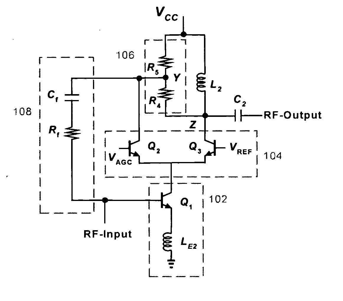
[0015]FIG. 1 shows a circuit schematic of a continuous variable-gain LNA constructed in accordance with one embodiment of the present invention. The circuit of FIG. 1 includes an input transconductance stage 102, a current-steering circuit 104, and an output load network 106. The input stage consists of an inductively degenerated common-emitter transistor Q1 with its collector connected to the emitters of Q2 and Q3, which form the cascode current steering circuit. The output load network consists of resistors R4 and R5 connected in series between the supply voltage VCC and node Z. Transistors Q2 and Q3 are arranged in a common-base configuration with the collectors of Q2 and Q3 tied to output load network nodes Y and Z, respectively. The base of transistor Q3 is connected to a reference voltage VREF, while the base of Q2 is connected to the gain control voltage VAGC. A shunt feedback network 108 is connected from node Y of the load network to the base of the input stage transistor Q...


PUM


Abstract

Continuous variable-gain low-noise amplifier. The amplifier continuously adjusts its gain between well-defined high and low values by using a cascode current-steering circuit to partition signal current between two different nodes of an output loading network. A shunt feedback network connected from an intermediate node of the loading network to the input provides negative feedback that linearizes the amplifier as its gain is decreased. The circuit degrades the noise figure at lower gains by varying the gain without directly dumping the signal current to the power supply. The circuit produces only small changes in input and output impedances and preserves an improved reverse-isolation cascode characteristic as the gain is controlled.

Description

CROSS REFERENCE TO RELATED APPLICATIONS [0001] This Application is a Continuation of U.S. patent application Ser. No. 10 / 139,141 filed on May 3, 2002. The application Ser. No. 10 / 139,141 claims the benefit of priority from a U.S. Provisional Application entitled “CONTINUOUS VARIABLE-GAIN Low-NOISE AMPLIFIER” Ser. No. 60 / 289,047 filed on May 4, 2001, the disclosure of which is incorporated by reference herein in its entirety for all purposes.FIELD OF THE INVENTION [0002] This invention relates generally to low-noise amplifiers (LNAs), and more particularly, to an LNA that varies gain continuously with respect to a control voltage. BACKGROUND OF THE INVENTION [0003] Variable gain amplifiers (VGAS) are frequently used in modern radio receivers to amplify or attenuate incoming signals to properly drive an associated analog-to-digital converter (A / D). Typically, the variable gain is distributed among radio frequency (RF), intermediate frequency (IF), and low-frequency or baseband circuit...

Claims


Application Information

Patent Timeline
Patent Type & Authority Applications(United States)
IPC IPC(8): H03F1/22H03G1/00
CPCH03F1/22H03G1/0023H03F2200/372H03F2200/294
Inventor COSTA, DAMIANAUSTIN, JOSEPHGROE, JOHNFARIAS, MICHAEL
Owner QUINTIC MICROELECTRONICS WUXI
Why Eureka
Try Eureka