Fuel cell

a fuel cell and cell technology, applied in the field of fuel cells, can solve the problems of decreased durability, achieve the effects of reducing voltage, preventing contamination of cooling medium, and reducing corrosion curren

Inactive Publication Date: 2005-06-30
HONDA MOTOR CO LTD
View PDF1 Cites 18 Cited by
  • Summary
  • Abstract
  • Description
  • Claims
  • Application Information

AI Technical Summary

Benefits of technology

[0049] The present invention as described above may be useful when applied to a fuel cell having a structure in which not less than 50 unit power generation cells are stacked. As described below, the present invention uses the integrated liquid resistance (integrated value of the liquid resistance for each cell) of the cooling medium communicating hole penetrating plural layered cells, reduces the voltage applied to the cell disposed at a higher voltage side via the cooling medium, and thereby reduces the corrosion current which is remarkably generated at the higher voltage side. Therefore, in a case in which the number of layered cells exceeds a predetermined number, the effects can be remarkably obtained. As described below, the effect of inhibiting corrosion is obtained when the number of cells stacked exceeds about 50, and the effect is prominent when the number of cells stacked exceeds about 100.
[0050] According to the present invention, the voltage applied to the portion of the separator which is not covered with the insulating coating, via the cooling medium, can be reduced, so that the corrosion current can be inhibited and progress in corrosion can be inhibited. As a result, the contamination of the cooling medium can be prevented and formation of short circuits due to the contamination of the cooling medium can be prevented. The above cooling effect by the cooling medium can be obtained so that it is decreased.
[0051] Since the corrosion of the separator can be inhibited, decrease in thickness of the separator and decrease in strength of the separator can be avoided

Problems solved by technology

That is, when impurity ion metal ions are released from a separator surface contacting an acid solution, the electrolyte cata

Method used


Image

  • Fuel cell
  • Fuel cell
  • Fuel cell

Examples


first embodiment

(1) First Embodiment

[0066] In producing a fuel cell of a First Embodiment according to the present invention, in particular, the types of stainless steel plate as a separator substrate are not restricted as long as the stainless steel plate is a corrosion resistant under an atmosphere in which a fuel cell is used. Concretely, various ferrite-types, austenite-types, or a two phase-types of stainless steel can be used. The stainless steel plate desirably contains Cr of not less than 12 mass %. The thickness of the stainless plate is desirably 0.05 to 0.3 mm in consideration of assembly of the fuel cell.

[0067] A passivation film naturally generated in air is formed on a stainless steel separator surface under an environment in which the fuel cell is used. In the condition in which the above passivation film is naturally generated, an oxidation electrode side separator surface is sufficiently oxidation resistant even when exposed to an oxidation atmosphere. It is therefore not necessar...

examples 1 to 3

(A) EXAMPLES 1 TO 3 AND COMPARATIVE EXAMPLES 1 AND 2

[0070] The present invention will be described in detail hereinafter by way of Examples and Comparative Examples.

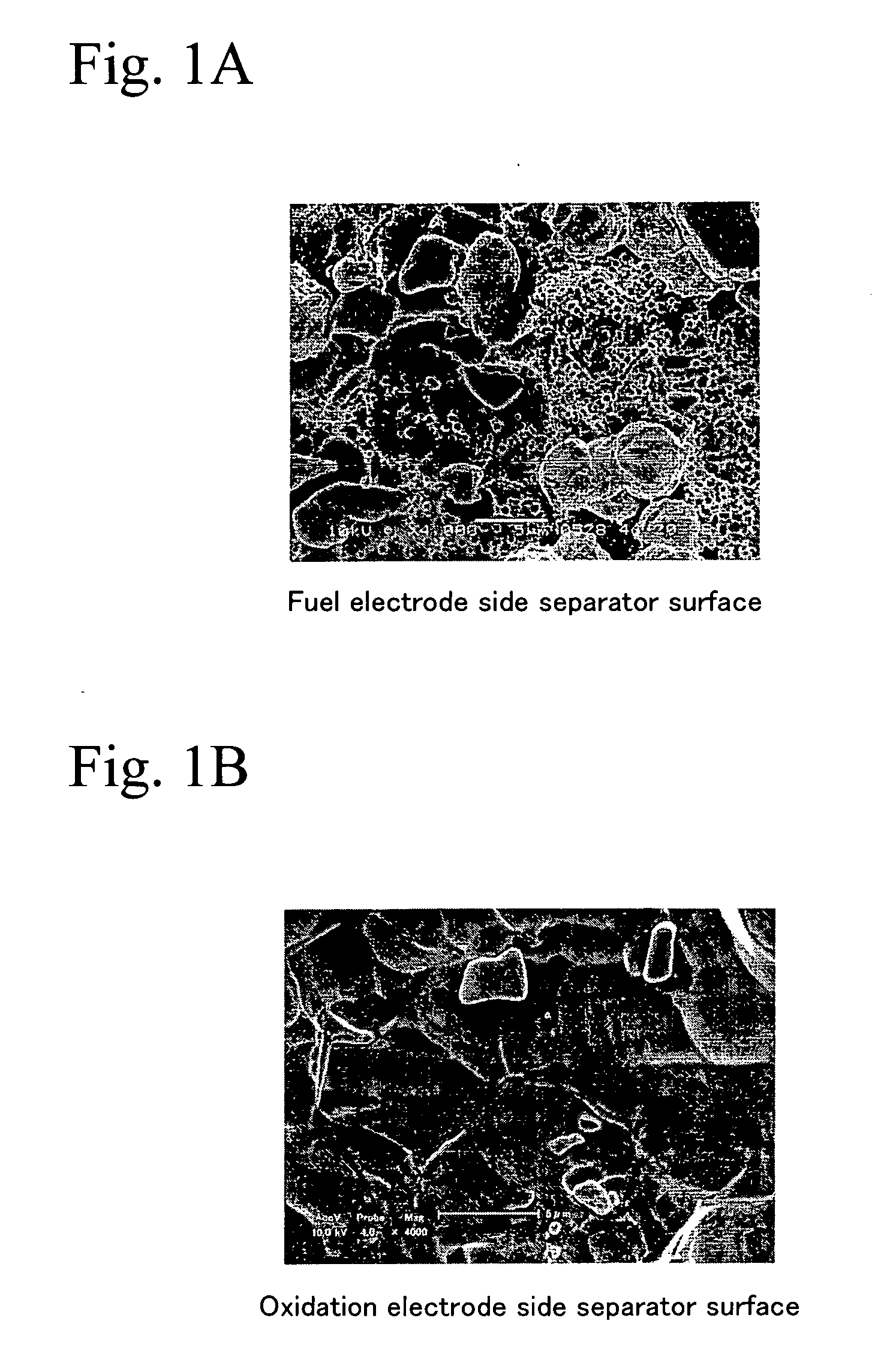
[0071] A passivation treatment performed on a stainless steel separator surface will be explained. In order to prevent release of metal ion impurities from a separator surface, the separator surface was subjected to a nitric acid, so that a passivation film was formed which was Cr-enriched. In Examples 1 to 3, a stainless steel having a composition shown in Table 2 was immersed in a nitric acid solution of 50 mass %. The immersing time was 5, 30, or 120 minutes. In Comparative Examples 1 and 2, a stainless plate which was not subjected to a passivation treatment and a stainless plate which was boiled in nitric acid solution of 50 mass % for 24 hours were used as a sample. Next, compositions of the above passivation films were analyzed by Auger Electron Spectroscopy. Table 3 shows measurement results of maximum ratio of ...

second embodiment

(2) Second Embodiment

[0085] A second preferred embodiment of the present invention will be described hereinafter with reference to the Figures.

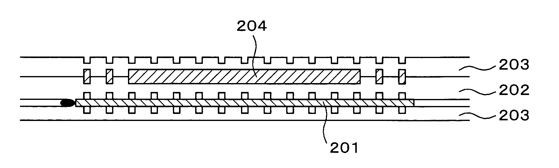
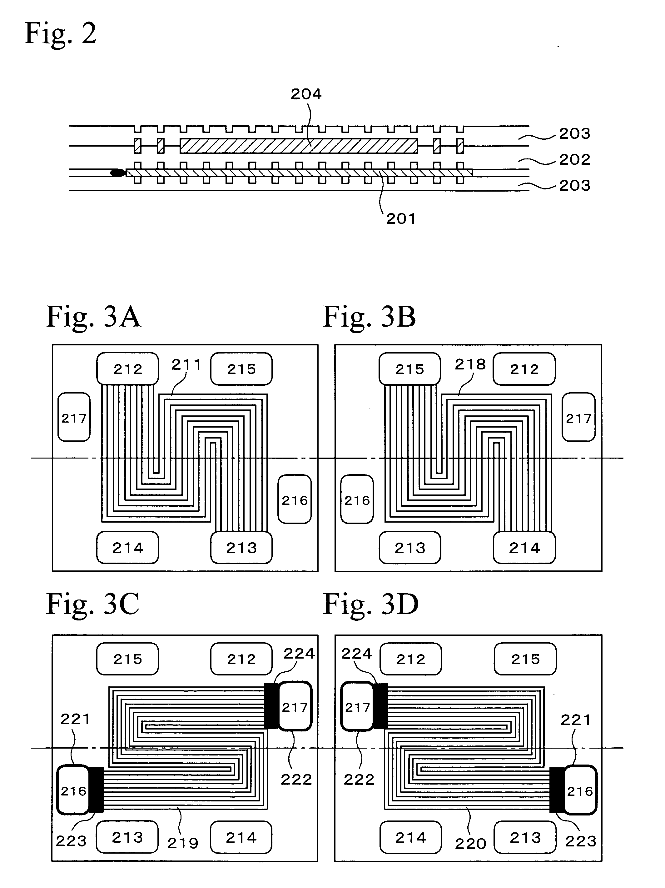
[0086]FIG. 2 is a cross sectional view showing a cell structure in a fuel cell of the Second Embodiment according to the present invention. As shown in FIG. 2, a cell has a MEA 201, an anode separator 202, a cathode separator 203, and a cooling medium 204. The anode separator 202 and the cathode separator 203 are opposite to both sides of the MEA 201. The cooling medium 204 is disposed between the anode separator 202 and the cathode separator 203 at a position in which a MEA is not disposed therebetween. A fuel cell of the Second Embodiment according to the present invention has a stacked structure such that the above plural cells are stacked.

[0087] In the above cell, cooling medium 204 is circulated between a surface opposite to a side of the anode separator 202 contacting the MEA 201 and a surface opposite to a side of the cathode separat...


PUM


Abstract

The present invention provides a fuel cell having a layered structure, including: a membrane electrode assembly having a fuel electrode, an oxidation electrode, and an electrolyte membrane held between the fuel electrode and the oxidation electrode; and stainless steel separators holding the membrane electrode assembly therebetween. The stainless steel separator contains Cr and Fe; the Cr concentration by mass % by mass ratio of Cr to Fe at the separator surface facing the fuel electrode is from 0.7 to 1.3; and the Cr concentration by mass % by mass ratio of Cr to Fe at the separator surface facing the oxidation electrode is less than 0.7.

Description

BACKGROUND OF THE INVENTION [0001] 1. Field of the Invention [0002] The present invention relates to a fuel cell, and in particular relates to a solid polymer electrolyte fuel cell. [0003] 2. Description of the Related Art [0004] In a fuel cell in which a polymer electrolyte is used, electric power and heat are simultaneously generated by an electrochemical reaction of a fuel gas containing hydrogen gas and an oxidizing gas containing oxygen gas or air. The fuel cell basically has a polymer electrolyte membrane for selectively transporting hydrogen ions, and a pair of electrodes, that is, an anode electrode and a cathode electrode formed on both surfaces of the polymer electrolyte membrane. The electrode generally consists of a catalytic layer formed on a surface of the polymer electrolyte membrane layer and a gas-diffusion layer formed on an outside surface of the catalyst layer. The catalyst layer is mainly composed of a carbon powder supporting a platinum group metal catalyst. Th...

Claims


Application Information

Patent Timeline
IPC IPC(8): H01M8/02H01M8/04
CPCH01M8/021H01M8/0228Y02E60/50H01M8/0267H01M8/04029H01M8/0263H01M8/241H01M8/2483H01M8/0258
Inventor TAKAI, TAKAHIROUTSUNOMIYA, MASAO
Owner HONDA MOTOR CO LTD
Why Eureka
Try Eureka