Method of coating a cutting tool

a cutting tool and coating technology, applied in the field of coating a cutting tool, can solve the problems of contaminated surface, renucleation tendency, industrial use of thicker pvd men- and/or me/sub>n-layers on cutting tools, etc., and achieve the effect of reducing compressive residual stress

Inactive Publication Date: 2005-07-07
SECO TOOLS AB
View PDF7 Cites 23 Cited by
  • Summary
  • Abstract
  • Description
  • Claims
  • Application Information

AI Technical Summary

Benefits of technology

[0011] The present disclosure provides a method to grow wear resistant nitride layers with reduced compressive residual stress, preferably based on Al and / or Si and / or Cr, onto cutting tools for machining by chip removal.
[0012] The present disclosure also provides a method to grow wear resistant nitride layers as microstructurally true single layers with a good coating thickness distribution.

Problems solved by technology

Secondly, if the deposition rate is decreased too much, and no ultra high vacuum deposition system is used, the surface can be contaminated during the coating-off period due to adsorption, which in turn enhances the renucleation tendency.
This means that commercial single layers are not true single layers but mostly multi-layer in the nanometer regime.
Industrial use of thicker PVD MeN- and / or Me2N-layers on cutting tools, has so far been strongly limited due to the compressive stresses normally possessed by such layers.
This effect is a limiting factor for the coating thickness of functional PVD-coatings.
However, none of these techniques is able to deposit a layer with low intrinsic compressive residual stress state with a maintained dense microstructure without induced defects caused by the rotation of the substrates.

Method used


Image

  • Method of coating a cutting tool
  • Method of coating a cutting tool
  • Method of coating a cutting tool

Examples


example 1

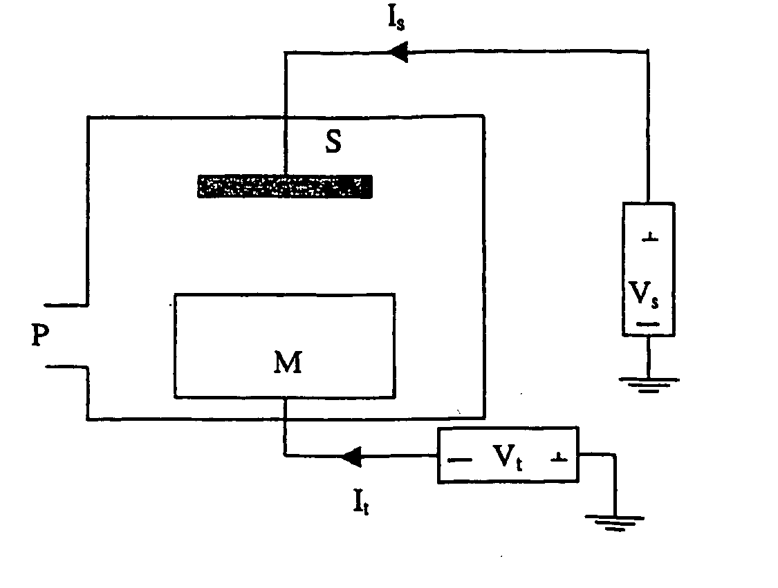
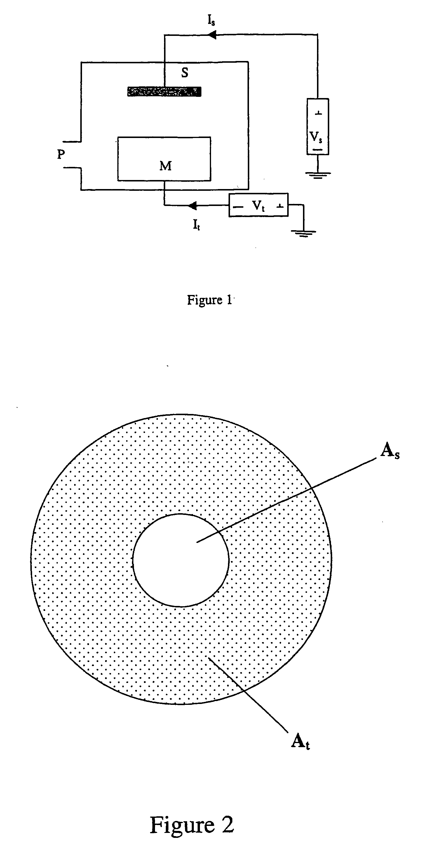
[0042] (Ti,Al)N-layers were deposited in a deposition system equipped with a rectangular dc magnetron sputter source with a Ti+Al target (50 at % Ti+50 at % Al) of 318 cm2. The substrate table projected surface area was 20 cm2 positioned at a distance of 5 cm from the target surface.

[0043] Mirror-polished cemented carbide substrates with composition 6 wt % Co and 94 wt % WC were used. The WC grain size was about 1 μm and the hardness was 1650 HV10.

[0044] Before deposition, the substrates were cleaned in an ultrasonic bath of an alkali solution and in alcohol. The substrates were stationarily positioned above the magnetron and resistively heated by an electron beam for 40 min to about 400° C. Immediately after heating, the substrates were argon-ion etched (ion current density 5 mA / cm2) for 30 minutes using a substrate bias of −200V. The subsequent (Ti,Al)N deposition was carried out by reactive magnetron sputtering using a magnetron power of 5 kW, an Ar pressure of 0.3 Pa, a nitrog...

example 2

[0050] In order to determine the N2 flow rate to obtain a stoichiometric ratio between the metallic elements and nitrogen, i.e., (Ti+Al) / N˜1, a test was performed where the N2 flow rate was varied between 10 and 175 sccm. All other deposition data was kept constant, e.g., the magnetron power at 5 kW, the substrate bias at +50V, Ar pressure at 0.25 Pa. The deposition system set-up was the same as in Example 1. The content of Al, Ti and N in the layers was measured using EDS. The results are reported in Table 2 below and show that using the present methods a surprisingly high stability for the N2 flow rate is achieved. In the whole range between 30 sccm and 175 sccm, a stoichiometric composition is obtained, e.g., (Ti+Al) / N is about 1. This is an effect of the high substrate electron current, increasing the dissociation rate of the N2 molecule. No Ar was detected in any of the layers.

TABLE 2Dependence of stoichiometry ratio (Ti + Al) / N on N2 flow rateN2 flow rateTiAlNStoichiometryVa...

example 3

[0051] Cemented carbide cutting tool inserts from Example 1 (the same names of the variants are used) were used in a face milling cutting test, in solid and slotted work piece material, SS2541. The homogeneous cutting test (solid work piece) was made in a 60 mm wide plate and the interrupted cutting test was performed by using three 20 mm wide plates separated by 10 mm, mounted as a package. The cutting data were; vc=250 m / min (homogeneous) and 200 m / min (interrupted), f=0.1 mm / rev and depth of cut=2.5 mm.

TABLE 3Face Milling Cutting TestHomogeneous cutInterrupted cutVariantTool life, mmTool life, mmAPrior art (Ti, Al)N22001500B(Ti, Al)N1700900(Vs = −100 V)DPresent invention28002100(Ti, Al)N(Vs = +50 V)

[0052] This test demonstrates that the variant D shows the best wear resistance, but also surprisingly the best toughness in spite of the thickest coating.


PUM

PropertyMeasurementUnit
current densityaaaaaaaaaa
deposition rateaaaaaaaaaa

Abstract

A method of depositing a nitride-based wear resistant layer on a cutting tool for machining by chip removal using reactive magnetron sputtering has a deposition rate, td, higher than 2 nm / s, a positive bias voltage, Vs, (with respect to ground potential) between +1 V and +60 V applied to the substrate, a substrate current density, Is / As, larger than 10 mA / cm2, a target surface area, At, larger than 0.7 times the substrate surface area, As, and a distance between the target surface and the substrate surface, dt, less than (At)0.5.

Description

RELATED APPLICATION DATA [0001] This application is based on and claims priority under 35 U.S.C. §119 to Swedish Application No. 0303485-7, filed Dec. 22, 2003, the entire contents of which are incorporated herein by reference. FIELD OF THE INVENTION [0002] The present disclosure relates to a method of coating a cutting tool, aimed for machining by chip removal, with a hard and wear resistant nitride layer with low compressive stress. The method for deposition is characterized by the use of reactive magnetron sputtering using a substrate holder, whose projected area is small compared to the target area, and by a high electron density current through the substrate, obtained by applying a positive substrate bias. STATE OF THE ART [0003] In the discussion of the state of the art that follows, reference is made to certain structures and / or methods. However, the following references should not be construed as an admission that these structures and / or methods constitute prior art. Applica...

Claims


Application Information

Patent Timeline
Patent Type & Authority Applications(United States)
IPC IPC(8): C23C14/00C23C14/06C23C14/35
CPCC23C14/0036C23C14/35C23C14/0641
Inventor KARLSSON, LENNART
Owner SECO TOOLS AB
Why Eureka
Try Eureka