Method for analysis of cell structure, and cell structure

Active Publication Date: 2005-09-01
NGK INSULATORS LTD
View PDF3 Cites 10 Cited by
  • Summary
  • Abstract
  • Description
  • Claims
  • Application Information

AI Technical Summary

Benefits of technology

[0031] Since the method for analysis of a cell structure according to the present invention is performed by the macroanalysis step of calculating the stress distribution in the anisotropic solid body equivalent to the cell structure and the microanalysis step of calculating the stress distribution in the aimed cell structure selected based on the result of the macroanalysis step, the amount of calculation required for the stress calculation in each step can be significantly reduced. This is because the number of elements, the number of nodes, and the number of degrees of freedom of the finite element model in each step are significantly reduced. In the case where the number of elements, the number of nodes, and the number of degrees of freedom of the entire cell structure amount to several tens of millions, the number of elements, the number of nodes, and the number of degrees of freedom of the equivalent anisotropic solid body in the macroanalysis step may amount to several tens of thousands, although the numbers may differ depending on the conditions such as the cell pitch and the wall thickness of the cell structure. In the microanalysis step, since the stress is calculated as the cell structure, the number of nodes, the number of elements, and the number of degrees of freedom amount to several tens of thousands as in the macroanalysis step. However, since the target region is selected and limited, the number of elements, the number of nodes, and the number of degrees of freedom of the finite element model as the calculation target are significantly small in comparison with those of the entire cell structure.
[0032] If the target replaced with the anisotropic solid body in the macroanalysis step is the part of the cell structure which is a piece obtained by equally dividing the entire cell structure into two, four, or eight, which is the preferable mode of the present invention, the number of elements, the number of nodes, and the number of degrees of freedom of the finite element model can be further reduced in comparison with the case of replacing the entire cell structure with the anisotropic solid body, whereby the amount of stress calculation is reduced.
[0033] Therefore, the stress can be calculated by using commercially-available general-purpose computer software and hardware, and the time required for the processing is significantly r

Problems solved by technology

The stress which occurs inside the honeycomb structure due to the nonuniform temperature distribution or the external pressure may cause cracks to occur.
In particular, when the honeycomb structure is used as a filter (diesel particulate filter: DPF) for trapping particulate matter contained in exhaust gas from a diesel engine, since the honeycomb filter is regenerated by burning and removing the deposited carbon particulate matter, a local increase in the temperature inevitably occurs.
This increases the stress which occurs inside the honeycomb structure or on the outer wall (body face) or the end face, whereby cracks easily occur.
However, the above test method takes time, and poses limitations on possible test conditions.
However, when applying a finite element analysis method for analyzing the stress distribution in the honeycomb structure, since the honeycomb structure has a three-dimensional structure in which many minute cells are assembled, the amount of calculation is increased to a large extent, and it

Method used


Image

  • Method for analysis of cell structure, and cell structure
  • Method for analysis of cell structure, and cell structure
  • Method for analysis of cell structure, and cell structure

Examples


example 1

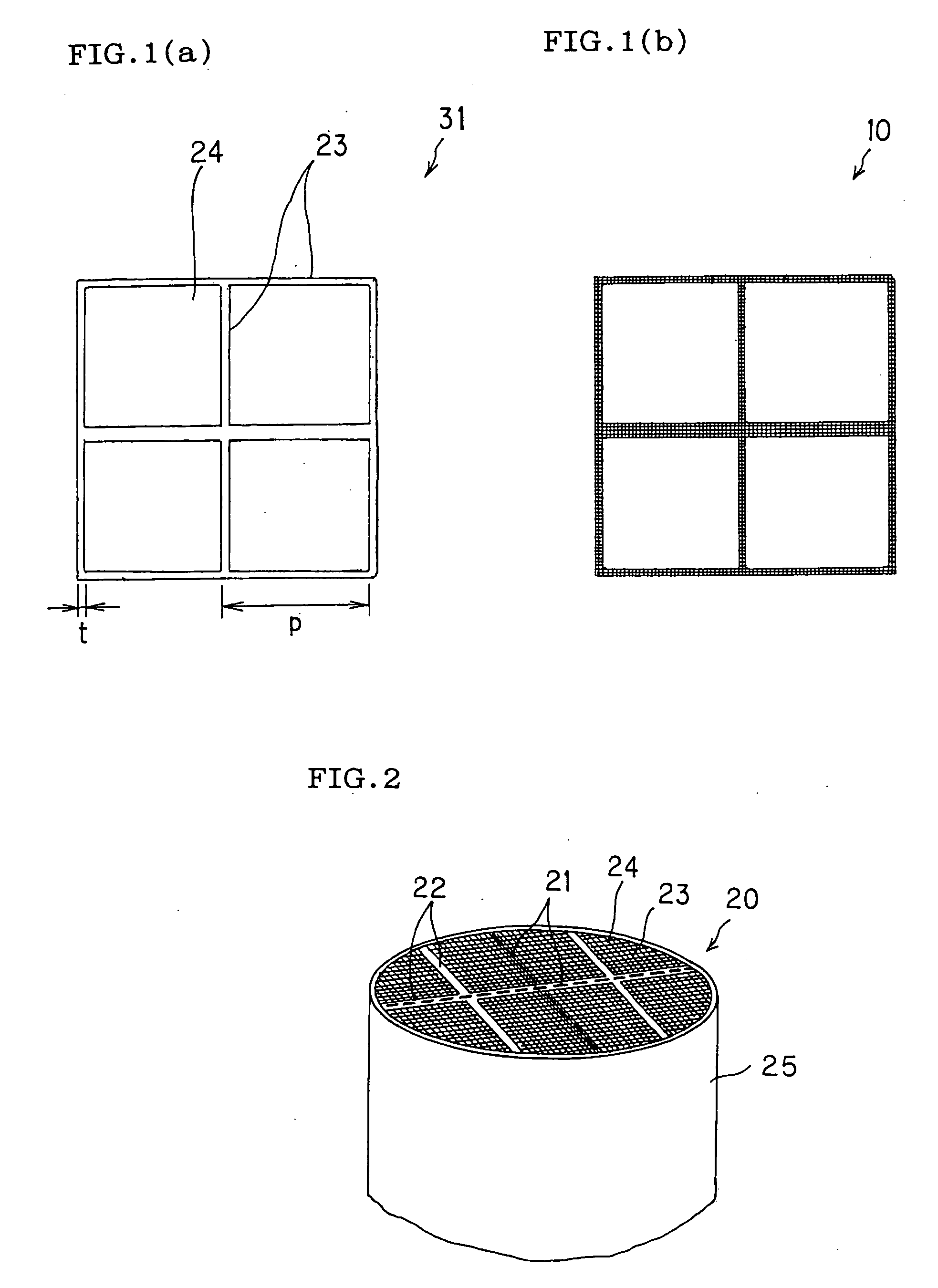
[0089] A honeycomb structure A in the shape of a tubular body having a circular cross-sectional shape was provided (not shown). The honeycomb structure A had a cross-sectional diameter of 25.82 mm and an axial length (height) of 10 mm. The cell pitch was 1.47 mm, the partition wall thickness was 0.3 mm, and the radius of curvature at the partition wall intersection was 0.06 mm.

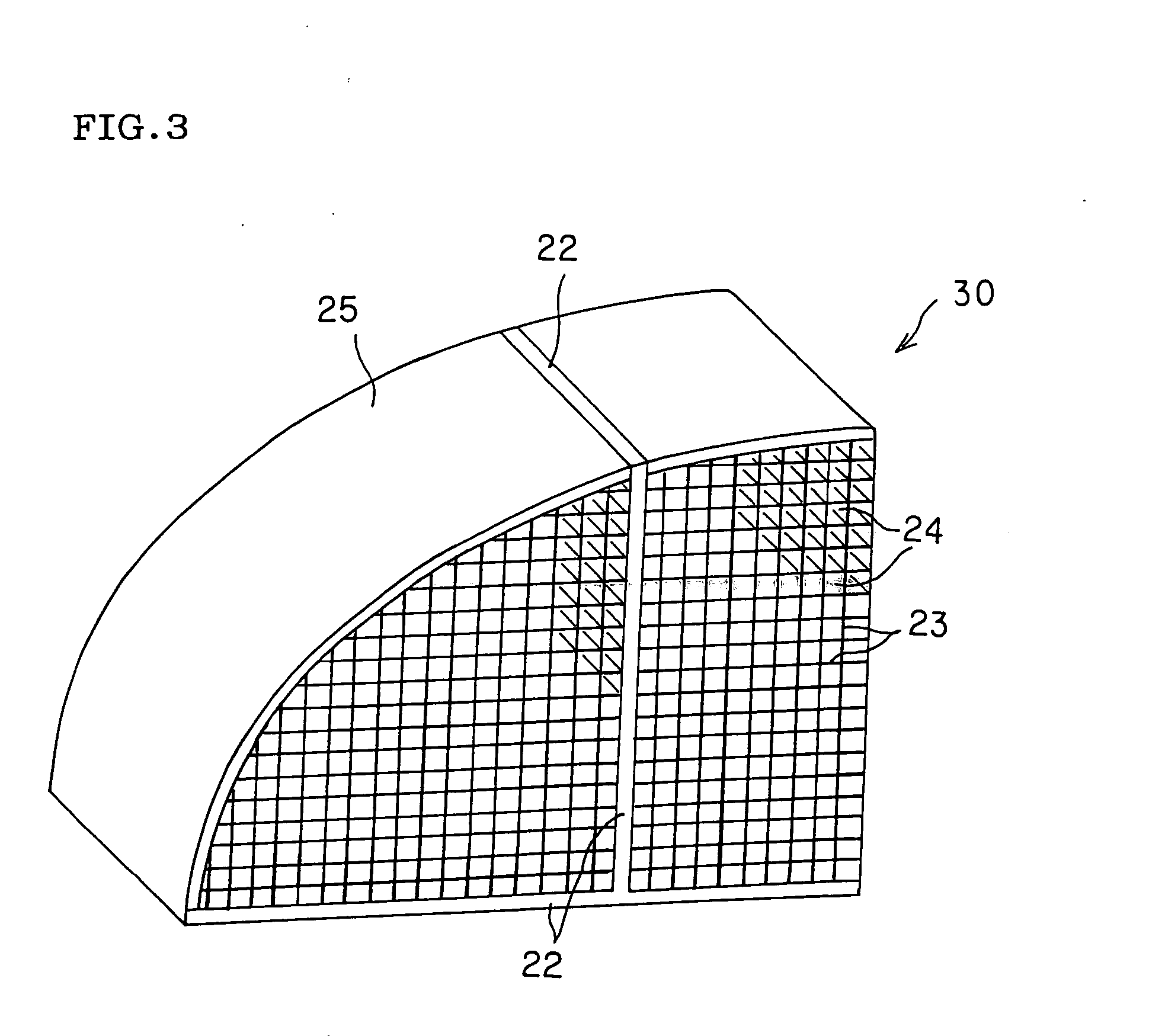
[0090] The macroanalysis was performed using a quarter piece of the honeycomb structure A. The quarter piece was replaced with an anisotropic solid body having equivalent rigidity characteristics using the numerical equation (1). The property values of the anisotropic solid body having rigidity characteristics equivalent to the rigidity characteristics of the honeycomb structure A were calculated from the mechanical properties and the dimensions as the honeycomb structure. As the mechanical properties of the honeycomb structure A at 25° C., a Young's modulus of 1 GPa, a Poisson ratio of 0.25, and a coefficien...

example 2

[0097] A honeycomb structure B in the shape of a tubular body having a circular cross-sectional shape was provided (not shown). The honeycomb structure B had a cross-sectional diameter of 20 mm and an axial length (height) of 10 mm. The cell pitch was 1.47 mm, the partition wall thickness was 0.2 mm, and the radius of curvature at the partition wall intersection was 0.5 mm.

[0098] The macroanalysis was performed using a quarter piece of the honeycomb structure B. The quarter piece was replaced with an anisotropic solid body having equivalent rigidity characteristics using the numerical equation (1). As the normalized mechanical properties of the honeycomb structure B at 25° C., a Young's modulus of 15, a Poisson ratio of 0.25, and a coefficient of thermal expansion of 1×10⁻⁶ were used for the partition wall, and a Young's modulus of 1, a Poisson ratio of 0.25, and a coefficient of thermal expansion of 1×10⁻⁶ were used for the outer wall.

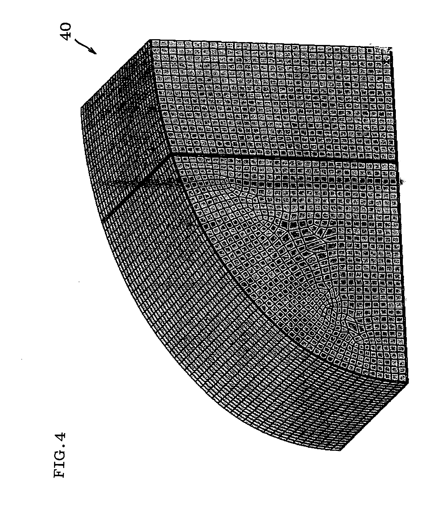
[0099] A finite element model of the replacem...


PUM


Abstract

A method for analysis of a cell structure includes a macroanalysis step and a microanalysis step. The macroanalysis step includes replacing a cell structure or a part of the cell structure with an anisotropic solid body having property values of equivalent rigidity characteristics, creating a finite element model of the anisotropic solid body based on the property values, applying an internal temperature distribution or an external pressure to the finite element model of the anisotropic solid body, determining the stress distribution in the anisotropic solid body, and selecting an aimed cell structure of which the stress should be calculated as a cell structure based on the stress distribution. The microanalysis step includes creating a finite element model of the aimed cell structure, and determining the stress distribution in the aimed cell structure based on the finite element model of the aimed cell structure. The structural analysis method is a means for analyzing the stress distribution in the cell structure due to the internal temperature distribution or external pressure which can be realized by using general-purpose computer software and hardware without performing a simulation test and making a large investment.

Description

BACKGROUND OF THE INVENTION AND RELATED ART [0001] The present invention relates to a method for analysis of a cell structure using a finite element method which is capable of efficiently and quickly determining the stress distribution which occurs inside the cell structure when a partial or nonuniform temperature change occurs inside the cell structure or when an external pressure is applied to the outer circumference (body face and end face) of the cell structure, and to a cell structure which has been subjected to stress analysis using the structural analysis method. [0002] A honeycomb structure as an example of the cell structure has been used as a catalyst substrate for an exhaust gas purification device used for a heat engine such as an internal combustion engine or combustion equipment such as a boiler, a liquid fuel or gaseous fuel reformer, or the like. The honeycomb structure is also used as a filter for trapping and removing particulate matter contained in dust-containing...

Claims


Application Information

Patent Timeline
IPC IPC(8): C12Q1/00G06F17/50
CPCG06F2217/80G06F17/5018G06F2119/08G06F30/23
Inventor ITOU, MOTOMICHIMIYAIRI, YUKIO
Owner NGK INSULATORS LTD
Why Eureka
Try Eureka