Polymeric foam powder processing techniques, foam powders products, and foams produced containing those foam powders

Inactive Publication Date: 2005-09-22
MOBIUS TECH
View PDF32 Cites 8 Cited by
  • Summary
  • Abstract
  • Description
  • Claims
  • Application Information

AI Technical Summary

Benefits of technology

[0018] This invention provides novel methods and devices for polymeric foam processing, particularly methods for comminuting (e.g., milling, pulverizing, or grinding) polymeric foams, preferably those containing with production

Problems solved by technology

Typical foam manufacturing processes result in polymeric foam wastes.
Post-consumer waste often contains contamination from other materials that were used in a fabricated part with the foam or from materials the foam was exposed to during its useful lifetime.
In addition to being reversibly deformable, flexible foams tend to have limited resistance to applied load and tend to have mostly open cells.
“Semi-rigid” or “semi-flexible” foams are those that can be deformed, but may recover their original shape slowly, perhaps incompletely.
Used foam objects, such as automobile cushioning materials, may be contaminated with grease or oil contaminants that destabilize the formation of new foam.
Foam trimmings containing polymeric foam skin waste material, which is typically formed in slabstock on the outside of a foam bun, are difficult to grind effectively using conventional grinding conditions that are most suitable for grinding polymeric foam.
The thermal insulating properties of foam make it difficult continuously to grind the foam in relatively long production runs because the grinding temperature tends to increase as grinding is continued, potentially resulting in thermal degradation of the polymeric foam.
Production contaminants result in increased grinding temperatures.
Furthermore, foam pieces and foam powder are difficult materials to handle in large quantities because these products bridge readily in various processing equipment.
Moreover foam powder tends t

Method used


Image

  • Polymeric foam powder processing techniques, foam powders products, and foams produced containing those foam powders
  • Polymeric foam powder processing techniques, foam powders products, and foams produced containing those foam powders
  • Polymeric foam powder processing techniques, foam powders products, and foams produced containing those foam powders

Examples


Example

Example 1

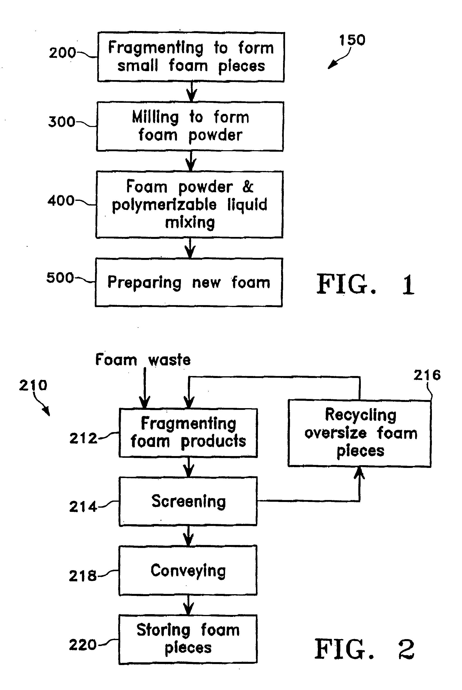
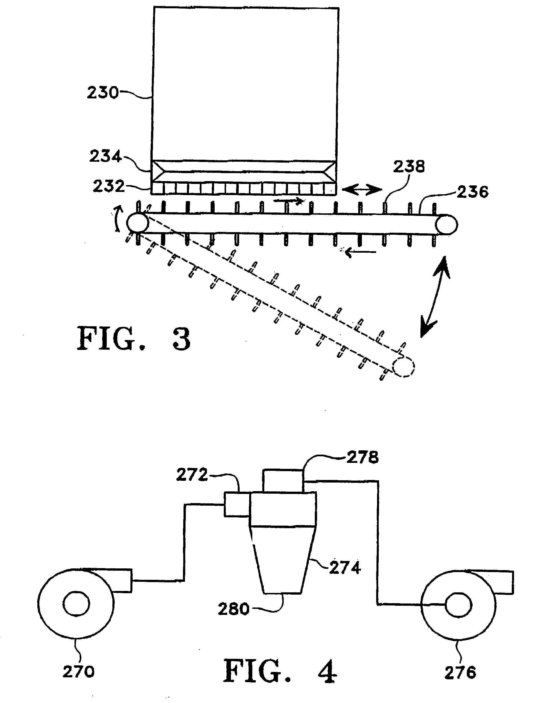
[0116] Flexible-slabstock polyurethane foam production scrap was obtained from trimming the skins from foam buns. The scrap contained dense skin material and polyethylene film, with the balance being polyurethane foam of varying density. This scrap material was first reduced to pieces with a size of approximately 1 cm. The foam pieces were then comminuted on 56-cm-diameter, 152-cm-length counter-rotating rolls such as those shown in FIG. 11 with speeds of 27 and 80 rpm. The resulting material was scraped together and quenched as it exited the rolls, and exposed to a turbulent air flow at room temperature. The material was discharged together with the air flow and conveyed to a sifter. The material was screened in the sifter, resulting in a fine foam powder having the particle-size distribution shown in Table 1. A coarse fraction that was also obtained from the sifter was returned to the counter-rotating rolls. The fine foam powder collected from the sifter was subsequently...

Example

Example 2

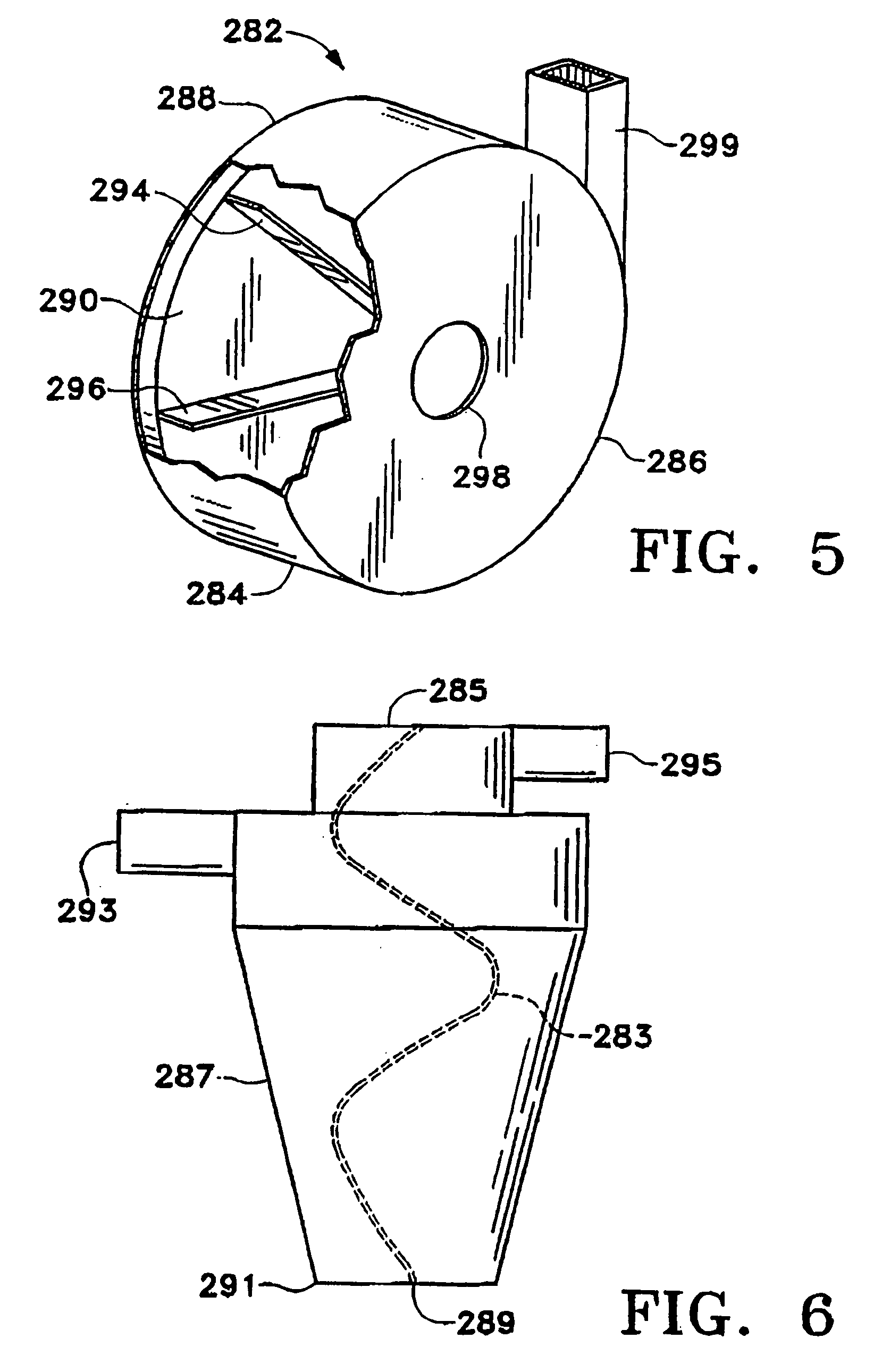
[0117] Flexible-slabstock polyurethane foam production scrap was obtained from trimming the skins from buns of foam made with polyether polyols. The scrap material included 2.3% by weight of high-density polyethylene film with a thickness of about 25 microns, and 30% by weight of dense skin material, with the balance being polyurethane foam of varying density. This scrap material was first reduced to pieces with a size of approximately 3 cm by means of a rotary grinder. The foam pieces were then comminuted on 30-cm-diameter, 45-cm-length counter-rotating rolls such as those shown in FIG. 11 with speeds of 30 and 120 rpm. The resulting material was scraped together and quenched as it exited the rolls, and exposed to a turbulent air flow at room temperature. The material was discharged together with the air flow and conveyed to the inventive sifter as shown in FIG. 13A. The material was screened in the sifter, resulting in a fine foam powder having the particle-size distribu...

Example

Example 3

[0118] A slurry sample was prepared by mixing 15 parts of the fine polyurethane powder described in Example 1 with 100 parts of VORANOL® 3137 polyether polyol from The Dow Chemical Company. This polyol is a liquid polyhydroxyl compound having a viscosity of about 460 centipoise at a temperature of 25° C.

[0119] The beneficial size reduction effects which are obtained by high-shear mixing of polyurethane powder in a polyhydroxyl compound are illustrated in FIGS. 22 and 23. After taking a small sample to measure particle size before high shear mixing, the remaining batch was subjected to 2.5 minutes of high shear mixing using a Silverson L4R laboratory high shear mixer. The mixer generates fluid shear by means of centrifugal action of a rotor in a high shear rotor / stator workhead. Particle size analysis was performed using a laser-diffraction technique with a Mastersizer 2000 from Malvern Instruments, Southborough, Md.

[0120] The results are shown in the graphs depicted in F...


PUM

PropertyMeasurementUnit
Fractionaaaaaaaaaa
Percent by massaaaaaaaaaa

Abstract

This relates variously to techniques for comminuting polymeric foams, to techniques for preparing polymeric foams containing that comminuted foam, and to the resulting comminuted foam powder and polymeric foams. The procedures may be used on foams containing production contaminants such as polyolefins, paper, and foam skins and on other foams containing consumer contaminants such as wood, metal, leather, etc. The comminuted foam powder, with or without contaminants, preferably is screened or sifted to obtain a foam powder having a particle size of about 2 mm or less.

Description

FIELD OF THE INVENTION [0001] This invention relates variously to techniques for comminuting polymeric foams, to techniques for preparing polymeric foams containing that comminuted foam, and to the resulting comminuted foam powder and product polymeric foams. The procedures may be used on foams containing production contaminants such as polyolefins, paper, and foam skins and on other foams containing consumer contaminants such as wood, metal, leather, etc. BACKGROUND OF THE INVENTION [0002] Polymeric foams include a wide variety of materials, generally forming two-phase systems having a solid polymeric phase and a gaseous phase. The continuous phase is a polymeric material and the gaseous phase is either air or gases introduced into or formed during the synthesis of the foam. Some of these gases are known as “blowing agents.” Some syntactic polymeric foams contain hollow spheres. The gas phase of syntactic foams is contained in the hollow spheres that are dispersed in the polymeric ...

Claims


Application Information

Patent Timeline
IPC IPC(8): B02C4/02B07B1/00B02C4/04B02C4/28B02C4/40B02C4/42B02C4/44B02C23/08B02C23/20B02C25/00B07B1/20B29B17/00B29B17/02B29B17/04B29K23/00B29K25/00B29K75/00C08G63/44C08J3/12C08J11/06C08L75/04
CPCB02C4/04C08J2475/04B02C4/42B02C25/00B07B1/20B29B17/00B29B17/02B29B17/0404B29B17/0412B29B2017/0203B29B2017/0224B29B2017/0484B29C44/3461B29K2023/06B29K2023/12B29K2025/00B29K2075/00B29K2105/04B29K2105/06B29K2105/065B29K2705/00B29K2705/12B29K2709/08B29K2711/12B29K2711/14B29L2007/00B29L2009/005B29L2031/44B29L2031/7322B29L2031/744C08G2101/0008C08G2101/005C08J3/12C08J11/06C08J2375/04C08L75/04B02C4/28C08J9/35C08L2666/20Y02W30/62Y02W30/52C08G2110/005C08G2110/0008
Inventor MARTEL, BRYANVILLWOCK, ROBERTSTONE, HERMAN
Owner MOBIUS TECH
Why Eureka
Try Eureka