Ion sources

a technology of ion sources and oxide layers, applied in the field of ion sources, can solve the problems of reducing the useful life of ion sources, contaminating ion sources, and actual presence of oxygen ions in the chamber, and achieve the effect of reducing the formation of said oxide layers

Active Publication Date: 2005-09-29
APPLIED MATERIALS INC
View PDF9 Cites 22 Cited by
  • Summary
  • Abstract
  • Description
  • Claims
  • Application Information

AI Technical Summary

Benefits of technology

[0019] The invention further provides an implantation apparatus comprising an ion source for generating a beam of ions desired for implantation into a substrate, the ion source containing an arc chamber having electrodes with exposed surfaces of a material which can react with oxygen to form an electrically non conducting oxide layer; a supply of a source gas containing atoms of oxygen; a source of displacement gas containing atoms of fluorine; an arc supply to apply an arc voltage between said electrodes

Problems solved by technology

However, in using carbon dioxide in an arc chamber, it has been found that the actual presence of oxygen ions in the chamber reduces the useful life of the ion source due to the production of stoichiometric and non-stoichiometric oxides of tungsten at the electrodes and, where other tungsten surfaces are present in the chamber, at those surfaces as well.
These oxides form within the chamber and it has bee

Method used


Image

  • Ion sources
  • Ion sources
  • Ion sources

Examples


Embodiment Construction

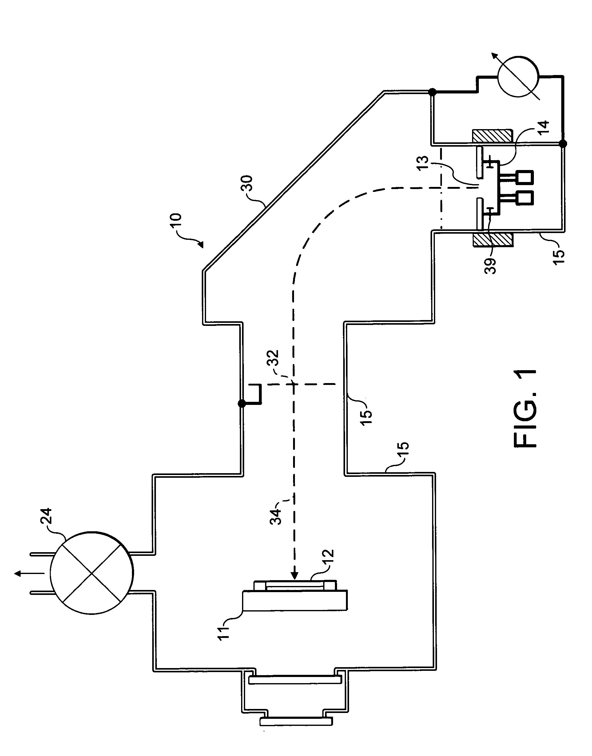
[0023]FIG. 1 illustrates an ion implantation apparatus generally indicated at 10. This apparatus is used for implanting ions into semiconductor substrates or wafers one of which is shown at 12 mounted on a support 11; the ions are produced by an ion source generally indicated at 14. The ions are directed in the form of a beam 34 by a mass-analyser generally indicated at 30 towards the substrate 12. Mass analysis is carried out by the analyser and then desired ions are selected by a slit 32 which only permits passage of ions having a desired mass / charge ratio to progress to the substrate. The ion source 14, mass analyser 30 and wafer support 11 are all mounted in a vacuum chamber 15 which is maintained under vacuum by one or more vacuum pumps, schematically indicated at 24.

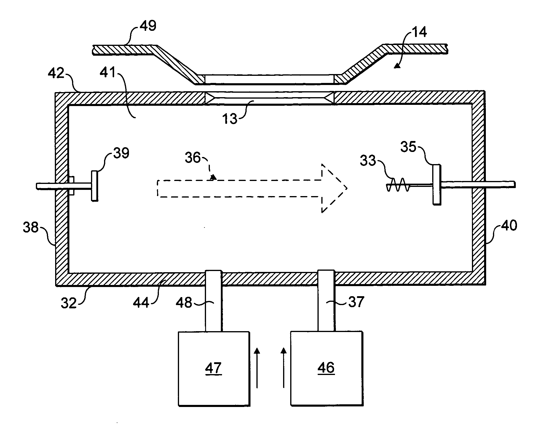
[0024] The ion source 14 is shown in greater detail in FIG. 2. Referring to FIG. 2, this illustrates in cross-section a Bernas ion source 14, viewed in section from one side in the drawing of FIG. 1. The ion sourc...


PUM


Abstract

The invention relates to methods of controlling the effect of ions of an ionisable source gas that can react with interior surfaces of an arc chamber, by introducing ions of a displacement gas into the arc chamber, where the displacement gas ions are more chemically reactive with the material of the interior surfaces than the ions of the source gas. The source gas ions may typically be oxygen ions and the displacement gas ions are then typically fluorine ions where the interior surfaces comprise tungsten. The fluorine ions may, by way of example, be sourced from fluorine, silicon tetrafluoride or nitrogen trifluoride.

Description

FIELD OF THE INVENTION [0001] This invention is concerned with improvements in or relating to ion sources particularly though not exclusively for use in or with implantation apparatus used to implant ions into semiconductor substrates in the manufacture of semiconductor devices. BACKGROUND OF THE INVENTION [0002] A typical ion source of the type with which the present invention is concerned comprises an ionisation, or arc, chamber (also sometimes referred to as a plasma chamber) into which source material can be introduced. A plasma is generated in the chamber in which the source material is ionised, and the ions are drawn off, by one or more extraction electrodes, through an outlet from the chamber. One typical ionisation chamber has a pair of cathodes arranged in opposed relationship, one referred to as a cathode and the other as a counter cathode. In use, the cathode is heated and emits electrons. The counter cathode then repels the electrons so that they are entrained between th...

Claims


Application Information

Patent Timeline
IPC IPC(8): H01J27/08H01J37/08H01J37/32
CPCH01J27/08H01J2237/31701H01J37/08H01J37/3171H01J37/32H01L21/265H01J27/02H01J37/30
Inventor BANKS, PETER MICHAEL
Owner APPLIED MATERIALS INC
Why Eureka
Try Eureka