Plasma display panel

a technology of display panel and plasma, which is applied in the direction of gas discharge vessel/container, electrodes, gas-filled discharge tubes, etc., can solve the problems of permanent residual image, low luminous efficiency, serious damage to the electrode, etc., and achieve the effect of increasing the aperture ratio and transmittance and extending the discharge area

Inactive Publication Date: 2005-09-29
SAMSUNG SDI CO LTD
View PDF17 Cites 10 Cited by
  • Summary
  • Abstract
  • Description
  • Claims
  • Application Information

AI Technical Summary

Benefits of technology

[0017] It is therefore, an object of the present invention to provide a plasma display panel (PDP) that can remarkably increase the aperture ratio and transmittance, compared with the conventional PDP and also remarkably extend a discharge area.
[0018] It is also another object of the present invention to provide a PDP that can efficiently use space charges of plasma by concentrating discharge plasma on a predetermined region of discharge space, for example, on a middle portion, operate at a low voltage, and remarkably reduce the permanent residual image phenomenon by substantially improving the luminous efficiency.
[0019] It is a further object of the present invention to provide a PDP with a structure that can reduce an outer reflection of an external light source and increase the reflection of visible rays emitted from the phosphor.
[0020] It is yet another object to provide a PDP through upper barrier ribs preventing external light from being reflected, bright room contrast is increased and visible rays excited from the phosphor layer are reflected so that brightness and color purity are enhanced, resulting in an increase in light efficiency.
[0021] It is a further object to provide a PDP through the structure of the PDP being much improved and the amount of plasma being greatly increased, much visible rays are emitted, brightness is increased, and a low voltage operation is possible, thereby increasing the luminous efficiency.

Problems solved by technology

The DC type PDP has a drawback in that the electrodes are seriously damaged because charges are directly moved between corresponding electrodes.
Also, the conventional surface discharge PDP 10 has a drawback that the luminous efficiency is low because electrodes generating a discharge are arranged on an upper surface of the discharge space, i.e., on an inner surface of the front panel 20 through which the visible rays pass so that the discharge is generated in the inner surface of the front panel 20.
Further, the conventional surface discharge PDP 10 may cause a permanent residual image because when the conventional surface discharge PDP 10 is used for a long time, charged particles of discharge gases generate ion sputtering in the phosphor due to an applied electric field.
As a result, the conventional surface discharge PDP 10 has a drawback that a contrast ratio is not high.
However, since the size of the non-discharge area is limited so as to maintain the aperture ratio above a predetermined value, there is a limitation in disposing the black stripe or increasing the line width of the bus electrode.

Method used


Image

  • Plasma display panel
  • Plasma display panel
  • Plasma display panel

Examples


Embodiment Construction

[0041] The present invention will now be described more fully with reference to the accompanying drawings, in which exemplary embodiments of the invention are shown.

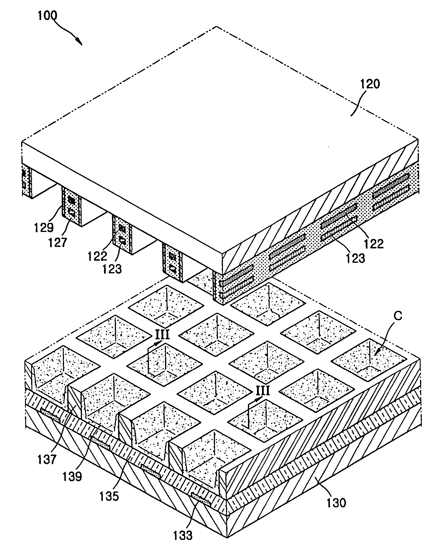
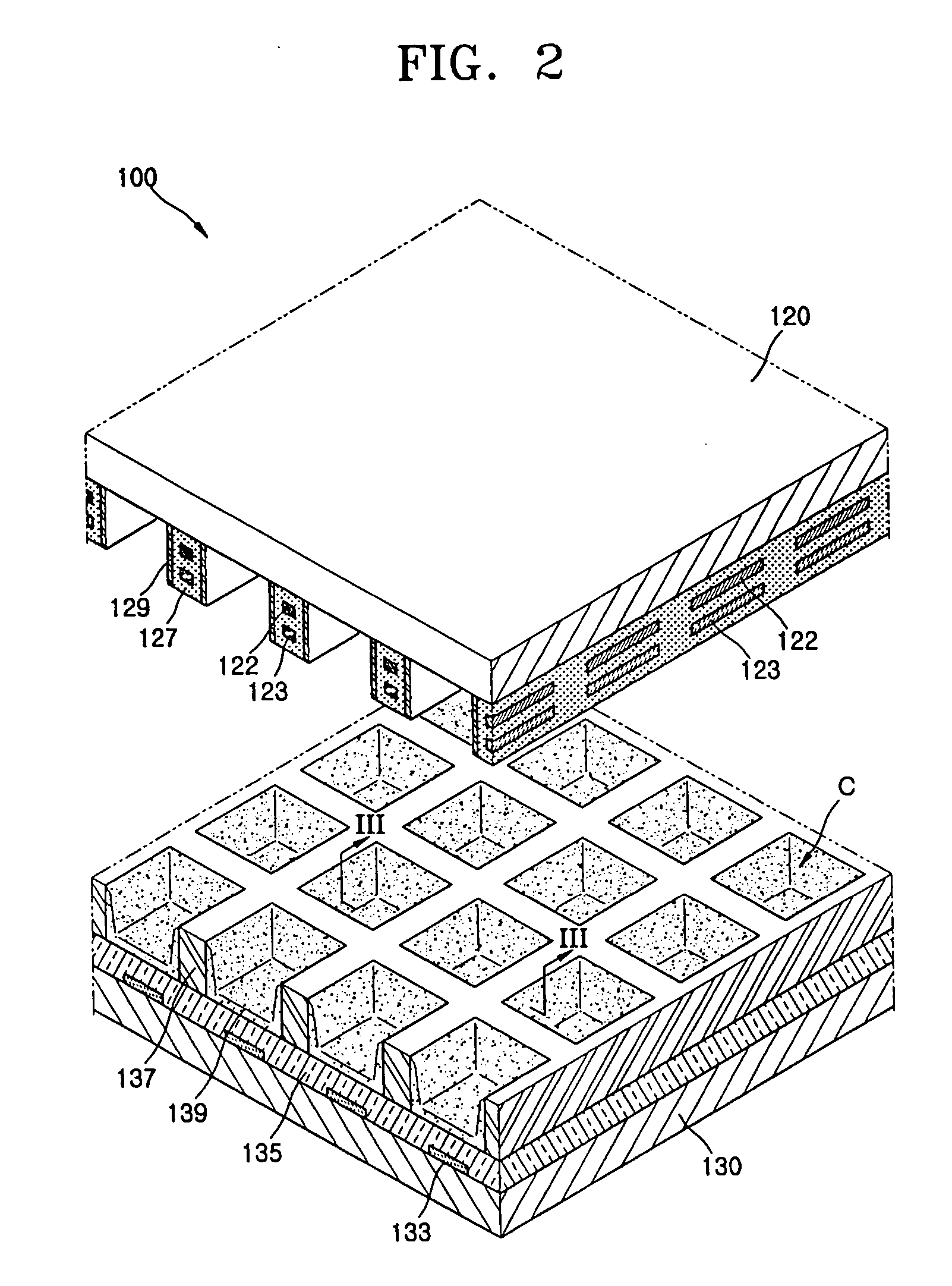
[0042] A Plasma Display Panel (PDP) according to a first embodiment of the present invention will now be described in detail with reference to FIGS. 2 through 4.

[0043] A PDP 100 according to a first embodiment of the present invention includes an upper panel (front panel) 120, a lower panel (rear panel) 130, upper barrier ribs 127, upper discharge electrodes 122, lower discharge electrodes 123, lower barrier ribs 137, phosphor layers 139, and a discharge gas (not shown).

[0044] The front panel 120 is transparent so that a visible ray is transmitted to project an image. The front panel 120 is arranged in parallel with the rear panel 130. The upper barrier ribs 127 are formed between the front panel 120 and the rear panel 130. The upper barrier ribs 127 are arranged at a non-discharge region to partition discharge cells....


PUM


Abstract

The present invention provides a plasma display panel (PDP) with a structure that can reduce an outer reflection of an external light source and increase the reflection of visible rays emitted from the phosphor, remarkably increase the aperture ratio of the front panel, and remarkably reduce occurrence of a permanent residual image. The PDP includes: a transparent front panel; a rear panel disposed in parallel with the front panel; a plurality of opaque upper barrier ribs disposed between the front panel and the rear panel to define a plurality of discharge cells, and formed of a dielectric material; a lower discharge electrode and an upper discharge electrode disposed within the plurality of opaque upper barrier ribs so as to enclose the discharge cells; a plurality of lower barrier ribs disposed between the plurality of opaque upper barrier ribs and the rear panel; a phosphor layer disposed within a space defined by the plurality of lower barrier ribs; and a discharge gas disposed inside the discharge cells.

Description

CLAIM OF PRIORITY [0001] This application makes reference to, incorporates the same herein, and claims all benefits accruing under 35 U.S.C. §119 from applications for PLASMA DISPLAY PANEL earlier filed in the Korean Intellectual Property Office on the 24 Mar. 2004 and there duly assigned Serial No. 2004-19982, and for PLASMA DISPLAY PANEL earlier filed in the Korean Intellectual Property Office on the 29 Mar. 2004 and there duly assigned Serial No. 2004-21151. BACKGROUND OF THE INVENTION [0002] 1. Field of the Invention [0003] The present invention relates to a Plasma Display Panel (PDP), and more particularly, to a PDP that forms an image by applying a discharge voltage to a plurality of electrodes arranged on two panels facing each other to generate ultraviolet rays which excite phosphor layers. [0004] 2. Description of the Related Art [0005] Recently, a flat panel display employing a plasma display panel (PDP) has been in the spotlight as a next generation display owing to super...

Claims


Application Information

Patent Timeline
Patent Type & Authority Applications(United States)
IPC IPC(8): H01J11/12H01J11/14H01J11/16H01J11/22H01J11/24H01J11/26H01J11/30H01J11/32H01J11/34H01J11/36H01J11/40H01J11/42H01J11/44
CPCH01J11/16H01J2211/366H01J11/36H01J11/30
Inventor KWON, JAE-IKKANG, KYOUNG-DOOYI, WON-JUAHN, JEONG-CHULLJUNG, EUN-YOUNG
Owner SAMSUNG SDI CO LTD
Why Eureka
Try Eureka