

Label-free high-throughput optical technique for detecting biomolecular interactions
a biomolecular interaction and optical technique technology, applied in the field of biosensors, can solve the problem of changing the resonance linewidth, rather than the resonance wavelength
- Summary
- Abstract
- Description
- Claims
- Application Information
AI Technical Summary
Benefits of technology
Problems solved by technology
Method used
Image

Examples
example 1
[0106] Five circular diffuse grating holograms were prepared by stamping a metal master plate into vinyl. The circular holograms were cut out and glued to glass slides. The slides were coated with 1000 angstroms of aluminum. In air, the resonant wavelength of the grating is ˜380 nm, and therefore, no reflected color is visible. When the grating is covered with water, a light blue reflection is observed. Reflected wavelength shifts will only be observable and measurable while the grating is covered with a liquid, or if a protein film covers the structure.
[0107] The purpose of this experiment is to immobilize both proteins and bacteria onto the surface of a grating at high concentration, and to measure the wavelength shift induced. For each material, a 20 ul droplet will be placed onto the active sensor area and allowed to dry in air. At 1 ug / ml protein concentration, a 20 ul droplet spreading out to cover a 1 cm diameter circle will deposit 2×10⁻⁸ grams of material. The surface dens...
example 2
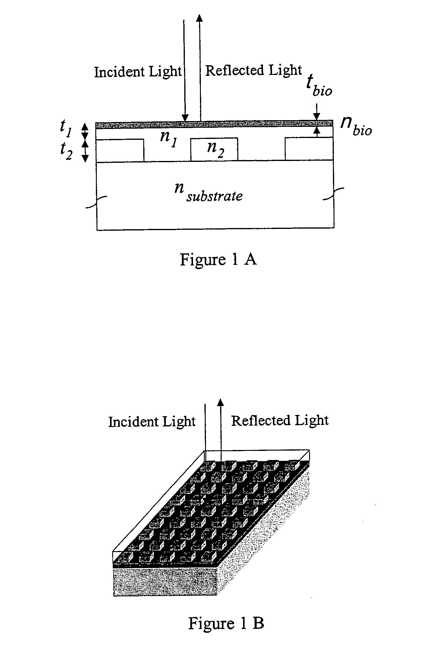
[0123] To demonstrate the concept that a resonant grating structure can be used as a biosensor by measuring the reflected wavelength shift that is induced when biological material is adsorbed onto its surface, the structure shown in FIG. 7 was modeled by computer. For purposes of demonstration, the substrate chosen was glass (nsubstrate=1.454) coated with a layer of silicon nitride (t3=90 μm, n3=2.02). The grating is two-dimensional pattern of photoresist squares (t2=90 nm, n2=1.625) with a period of 510 nm, and a filling factor of 56.2% (i.e. 56.2% of the surface is covered with photoresist squares while the rest is the area between the squares). The areas between photoresist squares are filled with a lower refractive index material. The same material also covers the squares and provides a uniformly flat upper surface. For this simulation, a glass layer was selected (n1=1.45) that covers the photoresist squares by t2=100 nm. To observe the effect on the reflected wavelength of this...
example 3
[0126] For a proteomics application, a biosensor array can be operated as follows: First, a biosensor array surface is prepared with an array of bait proteins. Next, the biosensor array is exposed to a test sample that contains a mixture of interacting proteins or a phage display library, and then this biosensor surface is rinsed to remove all unbound material. The biosensor chip is optically probed to determine which sites have experienced the greatest degree of binding, and to provide a quantitative measure of bound material. Next, the sensor chip is placed in a “flow cell” that allows a small (<50 microliters) fixed volume of fluid to make contact to the sensor chip surface. One electrode is activated so as to elute bound material from only a selected sensor array location. The bound material becomes diluted within the flow cell liquid. The flow cell liquid is pumped away from the sensor surface and is stored within a microtiter plate, or some other container. The flow cell liqui...
PUM
| Property | Measurement | Unit |
|---|---|---|
| thickness | aaaaa | aaaaa |
| diameter | aaaaa | aaaaa |
| diameter | aaaaa | aaaaa |
Abstract
Description
Claims
Application Information