Insulated RF suppressor for industrial magnetrons

a vacuum tube and suppressor technology, applied in the direction of transit tube leading-in arrangements, electrical/magnetic/electromagnetic heating, electrical apparatus, etc., can solve the problems of complex relationship between magnetic field strength, cathode bias voltage, filament current, and the geometry of the magnetron needed to establish a stable operating point of a specified rf output power and frequency, and achieve safer and more reliable operation, reduce the effect of cathode bias voltag

Inactive Publication Date: 2005-10-20
BURLE TECH LLC
View PDF7 Cites 9 Cited by
  • Summary
  • Abstract
  • Description
  • Claims
  • Application Information

AI Technical Summary

Benefits of technology

[0018] The present invention is directed to overcoming the problems associated with the known RF suppressors by use of an insulated RF suppressor that provides significant improvement with regard to tolerating higher cathode bias voltages. The insulated RF suppressor according to the present invention reduces magnetron failure rates and permits safer and more reliable operation at high microwave power levels.
[0019] The insulated RF suppressor according to the present invention is formed as a two-layered annular structure including an inner insulating sleeve and a coaxial outer RF absorbing shell. The inner sleeve of the RF suppressor is fabricated, by for example, machining or molding, from an electrical insulating material such as polytetrafluoroethylene (PTFE) and has a thickness of approximately 100 mils (about 2.5 millimeters). The outer shell is molded from the same or similar RF-absorbing material used in conventional magnetron RF suppressors. The PTFE sleeve provides a high degree of resistance to electrical breakdown at precisely the sites of the RF suppressor that are most susceptible to the adverse effects of high operating voltages. The use of the insulating inner sleeve realizes voltage break down characteristics that are significantly superior to those exhibited by conventional RF suppressors. At the same time, the molded outer cladding layer shell provides an RF absorbing function nearly equivalent to that attained in conventional RF suppressors that have no inner insulating sleeve. Thus, RF suppression is not unduly sacrificed in order to gain higher operating voltages.
[0020] The insulating inner sleeve may be fabricated, by for example, machining or molding, with a groove to seat the metal ring fixture that clamps the cathode for electrical contact and present a terminal post for can connecting the cathode voltage bias circuit and one lead of the filament circuit that heats the cathode. The screws, washers, and threaded holes used to fasten the cathode contact fixture to the RF suppressor are replaced with tabs in the insulating sleeve that hold the seated fixture in a groove formed on the edge of the RF suppressor insulated sleeve. The elimination of machined surfaces and the associated metal hardware is expected to provide further improvements in the voltage-hold off capability of an RF suppressor. Further, machined surfaces that absorb moisture and sharp edges that promote acing are eliminated in the RF absorber shell of the insulated RF suppressor.

Problems solved by technology

However, it is practically inevitable that some of the radiation generated by the magnetron will be transmitted to surrounding areas of the magnetron where it is neither utilized nor wanted.
This leakage radiation can interfere with electronics in the vicinity of the magnetron.
The relationship between magnetic field strength, cathode bias voltage, filament current, and magnetron geometry needed to establish a stable operating point of a specified RF output power and frequency is complex.
However, the present design trend is that high output power requires a higher magnitude cathode voltage bias between the cathode and the grounded anode.
The exact spatial distribution of this resultant electric field is difficult to predict, but it is evident, both intuitively and from experiment, that the sites that bear the largest magnitudes of the electric field, and hence are the most problematic with regard to high-voltage associated failures, occur near the terminal where the high-negative-voltage bias is applied to the cathode.
As evidence, it is noted that as the output power levels of some industrial magnetrons have increased from 30 kilowatts to 80 kilowatts in recent years, there has been a significant increase in the failure rate of the RF suppressor component of magnetrons due to the increased power levels and associated higher cathode bias voltages.
In many cases, the RF suppressor has proven to be the magnetron component that is most susceptible to high voltage breakdown effects, and is implicated as the dominant cause of failure in magnetrons operated at high power levels.
These stray currents induce RF fields in the upper portion of the magnetron tube and are the source of much of the spurious radiation leakage.
There is also RF radiation leakage due to electromagnetic radiation generated in the magnetron resonant cavity that emanates through the ceramic insulator components that are situated between the cathode connector pieces and grounded anode.
A choke mechanism attenuates, but does not completely eliminate, these effects.
This associated circuitry, i.e., the controlled power supplies, sampling circuits, current protection devices, RF relays, arc detectors and the like, is susceptible to interference associated with RF radiation leakage from the magnetron.
Virtually all materials exhibit some type of failure or breakdown when immersed in an electric field of sufficiently high field strength.
The failure phenomena, in some cases classified as dielectric breakdown, often involve a combination of arcing and avalanche effects resulting in irreversible changes in materials properties, and invariably rendering the material unsuitable for continued use.
Further, when the magnetron is turned on, there is a transient electric field due to overshoot of the power supply used to bias the cathode.
The resultant electric field distribution from all of these contributions can be complex, but it is generally true that regions of comparatively high electric field strength occur in the vicinity of the cathode connection to its voltage bias supply.
These regions of concentrated electric field strength, should they occur within or near materials with relatively low breakdown-voltage characteristics, are susceptible to damage.
Although the arc is eventually extinguished when the over-current protection device on the cathode power supply shuts the cathode voltage supply off, significant damage will still have occurred to the suppressor material.
Moreover, the magnetron itself is often damaged.
The ceramic-to-metal seal on the magnetron choke is often damaged to a degree that results in loss of magnetron tube vacuum.
When a vacuum tube loses its vacuum seal, it is no longer viable and must be rebuilt at considerable cost.

Method used


Image

  • Insulated RF suppressor for industrial magnetrons
  • Insulated RF suppressor for industrial magnetrons
  • Insulated RF suppressor for industrial magnetrons

Examples


Embodiment Construction

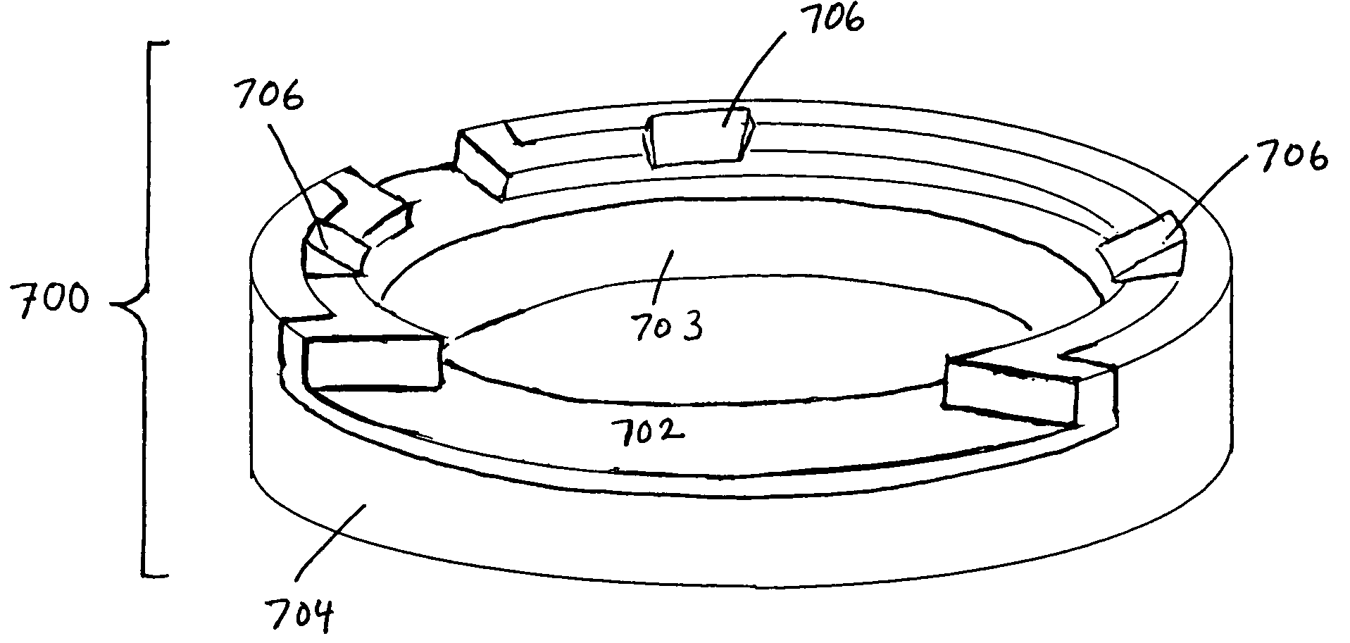
[0045] A new type of RF suppressor is described herein. By fabricating the RF suppressor component from two functionally distinct materials, the performance of the RF suppressor, particularly with respect to its high-voltage tolerance, can be enhanced compared to that of RF suppressors made from only one type of material. The present invention is an insulated RF suppressor that incorporates an inner sleeve of highly electrically resistive material that can withstand the application of very high electric fields. The insulated RF suppressor component is fabricated as a bilayer composite of two parts: an insulating member shaped from a polymer material such as PTFE, and an RF-absorbing member comprised of a suspension of iron particles in an epoxy resin and shaped by using the insulating member as part of a form to mold the RF-absorbing material. The resulting RF-suppressor is then a single-piece comprised of an annular-shaped insulating polymer sleeve with a molded RF-absorbing shell ...


PUM


Abstract

A radio-frequency (RF) radiation suppressor component for use with magnetrons that reduces spurious leakage radiation by absorbing RF radiation, that seats a metal ring connector fixture for making electrical contact to the cathode of the magnetron, and that exhibits improved tolerance of higher operating voltages. An insulated RF suppressor component is comprised of an insulating sleeve member and an outer shell cladding layer made of molded composite iron powder / epoxy resin material that absorbs part of the RF radiation and thus acts as an absorber to reduce magnetron radiation leakage. The insulating sleeve end has a ridged groove indentation to seat a metal clamping ring that contacts the magnetron cathode and provides a terminal connection for the cathode voltage bias and filament heating circuit leads. Testing of prototypes indicates significant improvement in permissible operating voltages and comparable RF suppression compared to conventional RF suppressor components currently in use.

Description

FIELD OF INVENTION [0001] This invention relates to magnetron microwave vacuum tube devices used to generate radio-frequency (RF) electromagnetic energy, and which find applications in microwave heating. More particularly, the invention relates to components used in magnetrons to suppress spurious radio-frequency energy transfer and to provide electrical insulation of electrodes; and further relates to designs and methods of construction to reduce failure rates of these components. BACKGROUND [0002] The magnetron is a well known vacuum tube electronic device used to generate radio-frequency (RF) electromagnetic energy. The magnetron was invented by Hull in 1921, and came into rapid development during the Second World War as a high-power microwave generator for radar transmitter applications. Currently, magnetrons are in widespread use for microwave cooking, thawing, tempering, drying of materials such as textiles and lumber, and other industrial and laboratory heating processes such...

Claims


Application Information

Patent Timeline
Patent Type & Authority Applications(United States)
IPC IPC(8): H01J23/15H05B6/72
CPCH05B6/72
Inventor REGAN, MICHAEL
Owner BURLE TECH LLC
Why Eureka
Try Eureka