

Power amplifier
a power amplifier and amplifier technology, applied in the direction of amplifiers with semiconductor devices/discharge tubes, amplifier combinations, printed circuit structure associations, etc., can solve the problems of low efficiency, difficult to achieve high efficiency, complicated configuration of divider circuits and combiner circuits, etc., and achieve high efficiency
- Summary
- Abstract
- Description
- Claims
- Application Information
AI Technical Summary
Benefits of technology
Problems solved by technology
Method used
Image

Examples
first embodiment
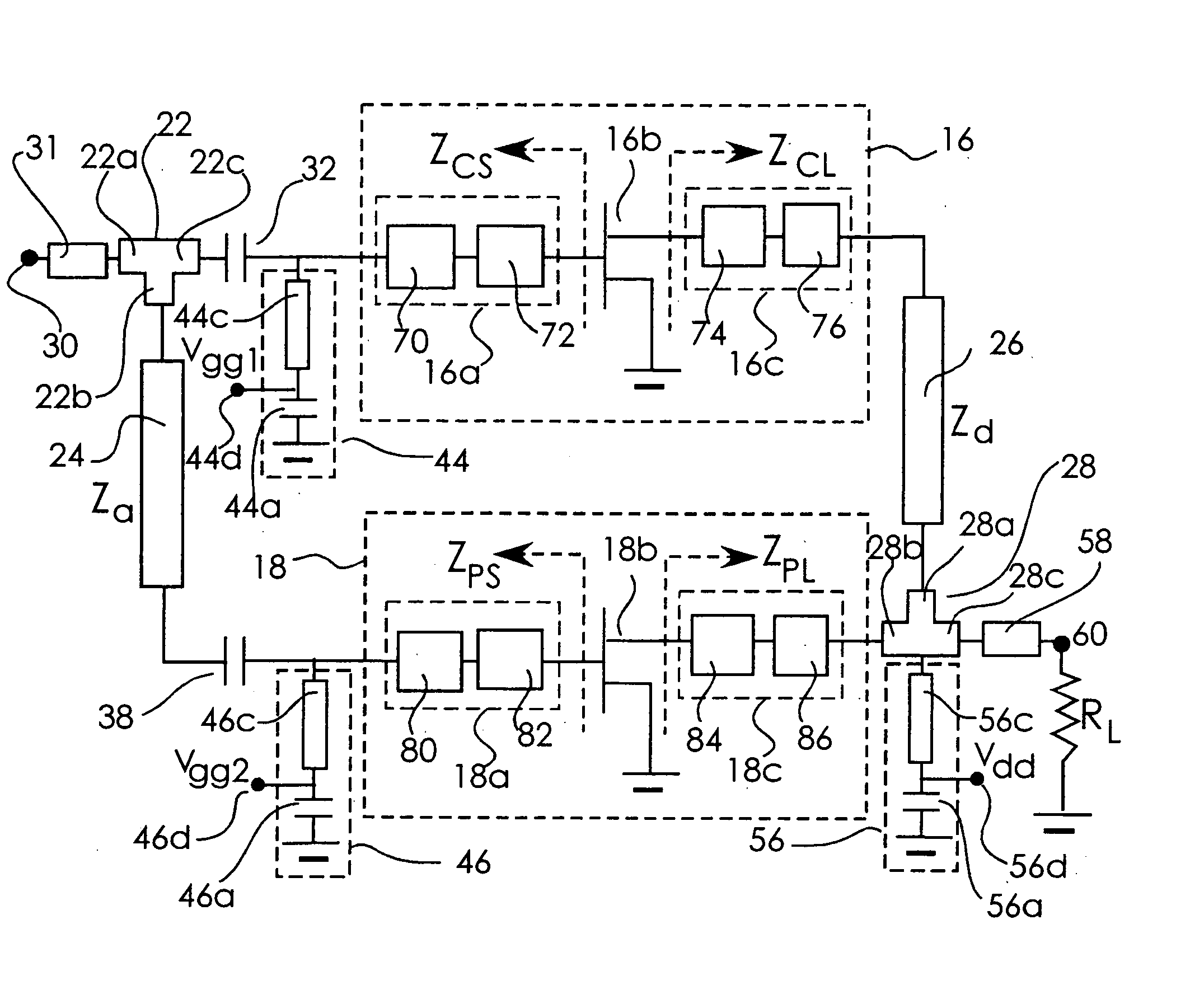
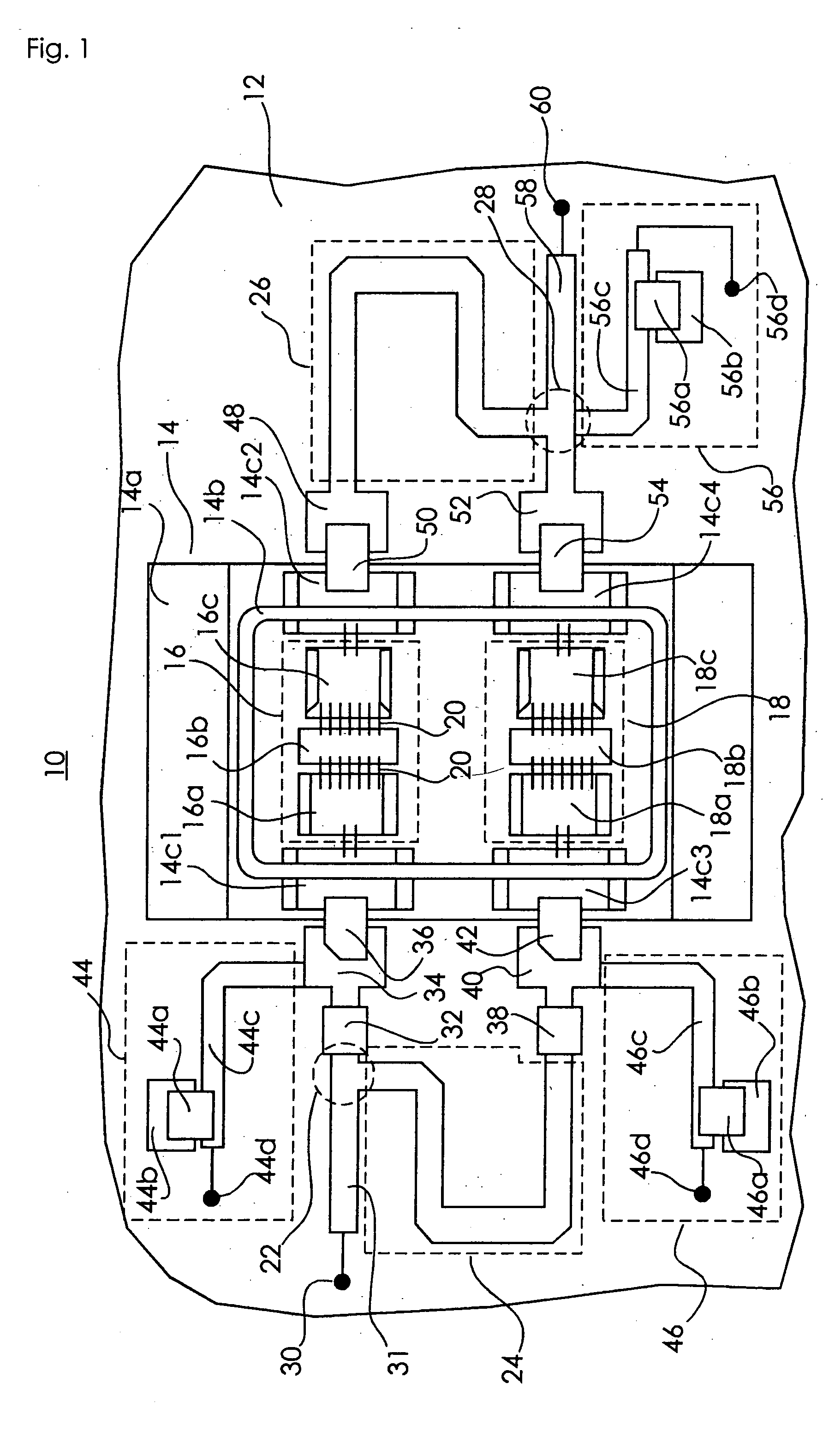
[0051]FIG. 1 is a plan view of a high-frequency power amplifier according to one embodiment of the present invention.
[0052] Referring to FIG. 1, a Doherty amplifier 10, which is an example of the first embodiment, uses a board 12 formed of, for example, a polytetrafluoroethylene member (hereinafter referred to as “PTFE”) serving as a circuit board.
[0053] As a material for the circuit board, a dielectric having a specific inductive capacity of about 2 to about 5 is used. In addition to PTFE having a specific inductive capacity of about 2.6, glass epoxy or the like having a specific inductive capacity of about 4.4 may be used.
[0054] A metal package 14 formed of a copper-molybdenum laminated material or CuW is disposed on the PTFE board 12.
[0055] The package 14 includes a metal substrate 14a, a wall 14b that is formed on the metal substrate 14a to surround a central portion of the metal substrate, and four connecting terminals 14c (14c1, 14c2, 14c3, and 14c4) for connecting interna...
first modification
[0104]FIG. 12 is a circuit diagram showing a modification of the high-frequency power amplifier according to an embodiment of the present invention.
[0105] In a Doherty amplifier 88 shown in FIG. 12, the second branch of the divider circuit 22 is further split into two branches and the first branch of the combiner circuit is further split into two branches so as to connect another phase compensating circuit 24 and another peak amplifier 18 between the second branch of the divider circuit 22 and the first branch of the combiner circuit in parallel to a phase compensating circuit 24 and a peak amplifier 18 disposed between the second branch of the divider circuit 22 and the second branch of the combiner circuit in the Doherty amplifier 10 shown in FIGS. 1 and 2.
[0106] Thus, using a plurality of peak amplifiers 18 provides the same effect as that obtained by increasing the size of the second FET chip 18b of the peak amplifier 18, making it possible to improve the efficiency of the amp...
second embodiment
[0109]FIG. 13 is a plan view of a high-frequency power amplifier according to another embodiment of the present invention. FIG. 14 is a circuit diagram of a high-frequency power amplifier according to the embodiment of the present invention.
[0110]FIGS. 13 and 14 show a Doherty amplifier 90, which is an example of the second embodiment.
[0111] The Doherty amplifier 90 shares the same basic construction as the Doherty amplifier 10 according to the first embodiment. The Doherty amplifier 90 differs from the Doherty amplifier 10 in that the Doherty network 26, which is disposed on the PTFE board 12 in the Doherty amplifier 10, has been replaced by a smaller Doherty network 92, which includes a dielectric board 92a formed of a dielectric having a higher specific inductive capacity than that of the PTFE board 12. The dielectric board 92a uses, for example, barium titanate (BaTiO3) having a specific inductive capacity of approximately 38. A microstrip line 92b having an electrical length ...
PUM
 Abstract
Description
Claims
Application Information