[0009] This can be used to minimize down-time associated with the removal and related cleaning of uncured, partially cured or fully polymerized organic materials within the organic material deposition
station without having to rely on the use of chemical solvents or
abrasive mechanical wiping. Such a cleaning
system may, for example, use a
plasma source to enable in-situ cleaning and a concomitant minimization in the amount of time where the
system has to be under non-vacuum conditions. The organic material deposition station may also include an adjustable substrate transport path. For example, by allowing up and down movement of a portion of a substrate transport path relative to a deposition
nozzle, various operating
modes can be facilitated, including a relatively closed position for process stabilization, an intermediate position for normal organic material deposition and a full open position for evacuation of a chamber surrounding the
nozzle. A masking station configured to apply a
mask to the substrate prior to deposition of at least one of the organic
layers may also be included. Furthermore, this masking station may include
mask alignment features to promote more accurate placement of a
mask relative to the substrate. A magnetic clamp may also be used to keep the mask and the substrate properly aligned once they are connected to each other.
[0014] The device may further comprise at least one surface treatment mechanism configured to enhance the ability of individual
layers of the multilayer
coating to adhere to the substrate or an adjacent layer. For example, while the use of
sputtering (discussed above in conjunction with the deposition of an
inorganic layer onto a substrate) is beneficial, its use coincides with increases in temperature and
plasma energy. Special measures may be undertaken to avoid damage to the environmentally sensitive device (such as an organic
light emitting diode (
OLED)) that can otherwise arise from being exposed to the plasmas and / or temperatures of the sputter
coating process. Other deposition techniques, such as thermal
evaporation, promote the deposition of inorganic layers without subjecting the environmentally sensitive device being encapsulated to harsh environments, e.g., high temperatures and / or plasmas. By way of example, since thermal
evaporation is a currently-used approach for forming the metallic top
electrode of an
OLED, such an
inorganic layer deposition approach could also be used as an encapsulation-enhancement approach, such as to deposit a protective layer. Unlike commonly-used oxides, such as aluminum
oxide (Al2O3), that are applied by reactive
sputtering, inorganics such as
lithium fluoride (LiF) and
magnesium fluoride (MgF2) (both of which are optically transparent) can also be applied via thermal
evaporation to create a protective layer without having to
expose the environmentally sensitive device to the
plasma. Similarly, the approach could utilize an inorganic transparent
metal halide via thermal evaporation, a sputtered transparent inorganic or first deposited organic, or a simpler approach in which thermal evaporation is used for the first deposited inorganic. The latter would require a first deposited inorganic that can be applied by thermal evaporation and provide a combination of adhesion and transparency.
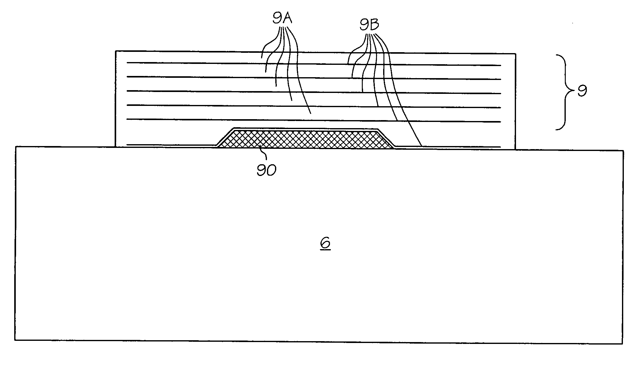
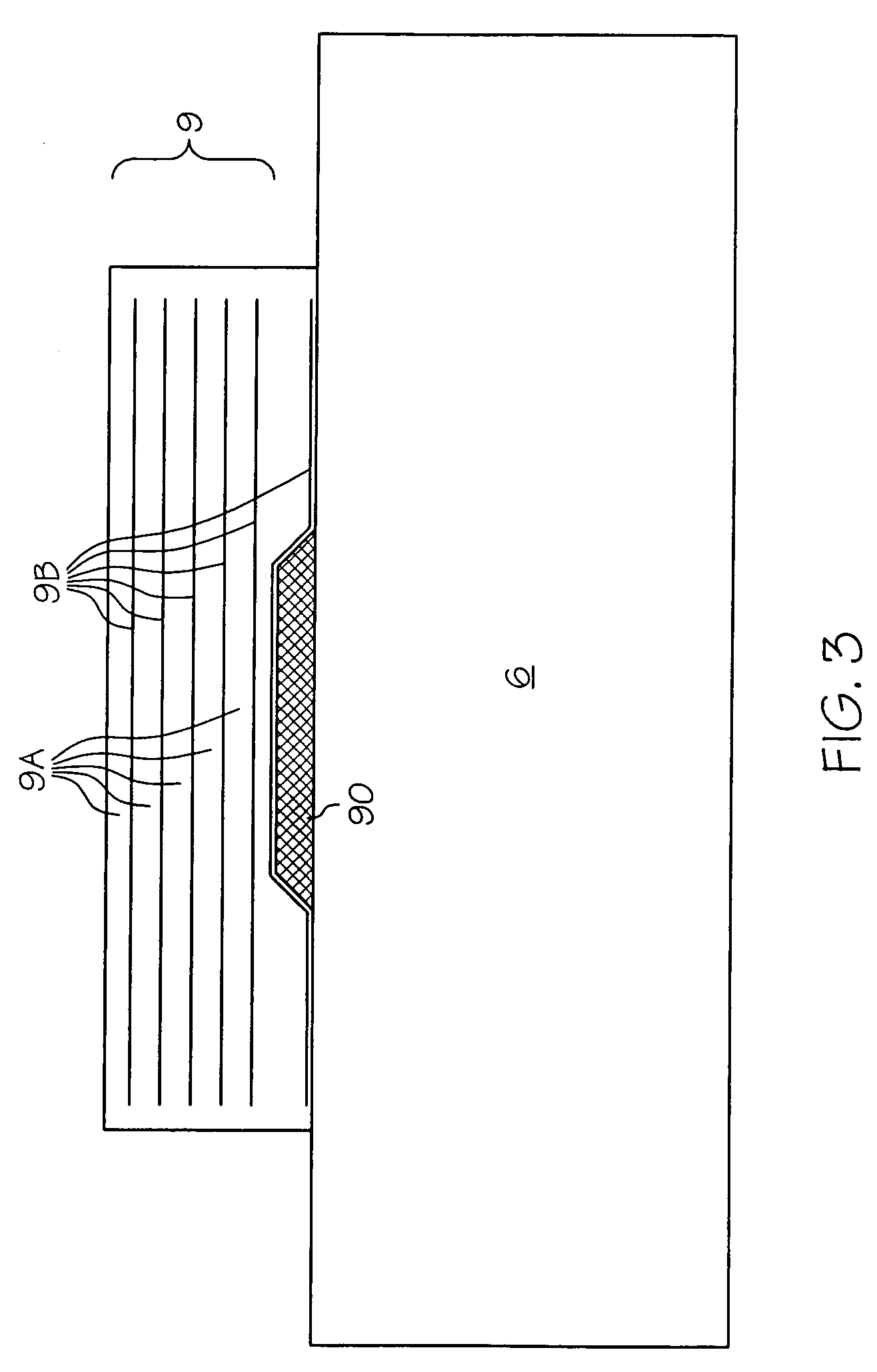
[0016] As stated above, the inorganic layer may be deposited onto the substrate prior to the placement of the
organic layer. The inventors have discovered that placing an inorganic (such as an
oxide) layer before placing an
organic layer results in improved adhesion between the substrate and between layers, as well as improved barrier properties. The inventors have further discovered that in situations involving encapsulation of an object (such as an
OLED) placed on the substrate, superior adhesion and barrier properties are achieved using such “inorganic first” approaches. Thus, while the inclusion of an organic layer continues to make valuable contributions to the overall performance of the multilayer coating, the inventors' research suggests that attainment of a suitable base (or foundation) for effectively isolating the barrier from undesirable contributions from the underlying substrate (or device) may be best achieved with one or more inorganic layer / organic layer pairs led by an inorganic layer (possibly on top of the aforementioned protective layer). By placing an inorganic layer onto a substrate (such as glass or a plastic) prior to the organic layer, the inventors have achieved adhesion to substrates, to devices placed on substrates, and between layers of multilayer environmental barriers, all of which withstand the physical and thermal rigors of the environment in which they have to perform. Furthermore, when these layers form the surface upon which a device is placed, they survive all of the
processing associated with fabrication of the device. The inventors believe that at least one explanation may be that migration of organic species from a plastic or related substrate to this first-applied layer is reduced compared to if the first layer is the organic layer, and that such migration reduction promotes and maintains enhanced adhesion between the substrate and the first-applied layer. In addition, in cases involving deposition onto a device mounted on the substrate, the inventors believe that with a first deposited organic layer, the layer does not adequately wet, or uniformly coat, the device surface. This could be due to species originating in the organic layers of the device being coated, not having a suitable formulation for the first deposited organic layer relative to the device, or a combination of both. On the other hand, an “organic first” approach (at least in encapsulation situations) would reduce or even eliminate the potential for damage to the device from the plasma used in depositing inorganic layers. As such, the choice of an “organic first” or an “inorganic first” deposition strategy can be made based on the particular needs of the substrate or device being coated.
[0017] As previously discussed, masks may be used to form particular deposition patterns on the substrate. To reduce the incidence of seepage and related capillary phenomena (which is especially prevalent when dealing with deposited organic layers), masks may be stacked to make an
undercut mask, or the organic mask may be removed prior to the curing step. Removal of the mask prior to cure may also improve cure speed by eliminating mask shadowing of the edge of the organic material.

