[0029] The
advantage of the present invention is not particularly restricted by the method for bonding the guidewire shaft (103, 203, 303, 403, or 503) to the main shaft (101, 201, 301, 401, or 501). Namely, if the guidewire shaft (103, 203, 303, 403, or 503) and the main shaft (101, 201, 301, 401, or 501) are composed of materials that can be welded to each other, bonding can be performed by a known method, such as a heat sealing process. Alternatively, if the guidewire shaft and the main shaft are composed of materials that cannot exhibit sufficient
bonding strength when welded, bonding may be performed by a method using an
adhesive or the like. In such a case, the
chemical species in the
adhesive used is not particularly limited. For example, a
cyanoacrylate, urethane,
epoxy, or
silicone adhesive is preferably used. The curing mechanism of the adhesive is also not particularly limited. For example, a
moisture-curing, two-part curing, or photo-curable adhesive is preferably used. If the guidewire shaft and the main shaft are composed of materials having poor adhesion properties, surface treatment may be performed, for example, by
oxygen plasma or
corona discharge, or using a
silane coupling agent.
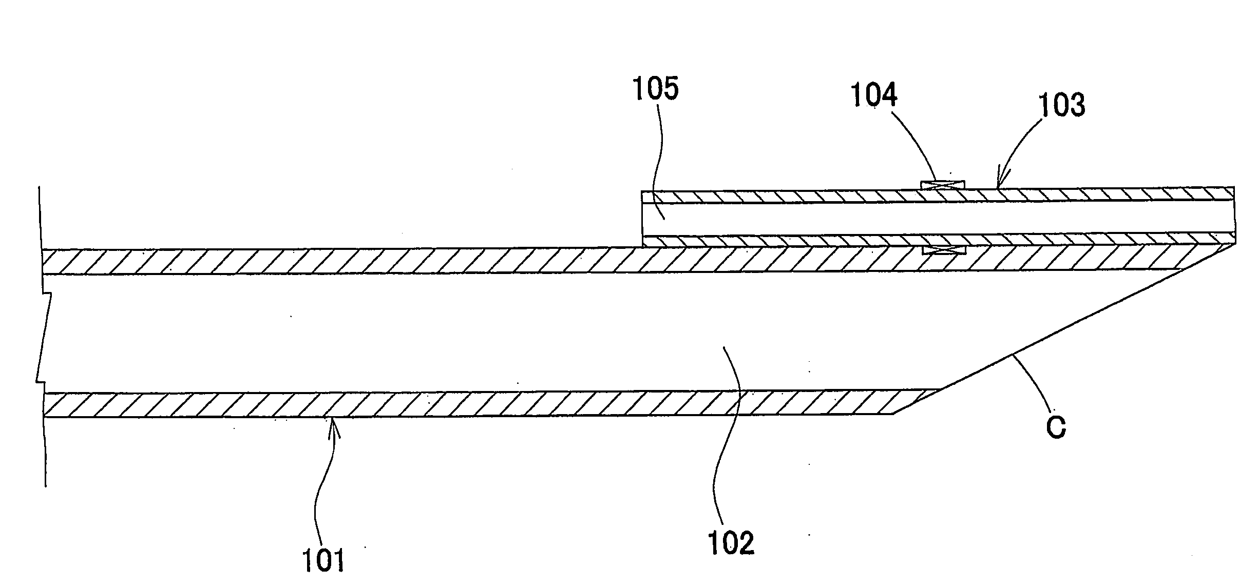
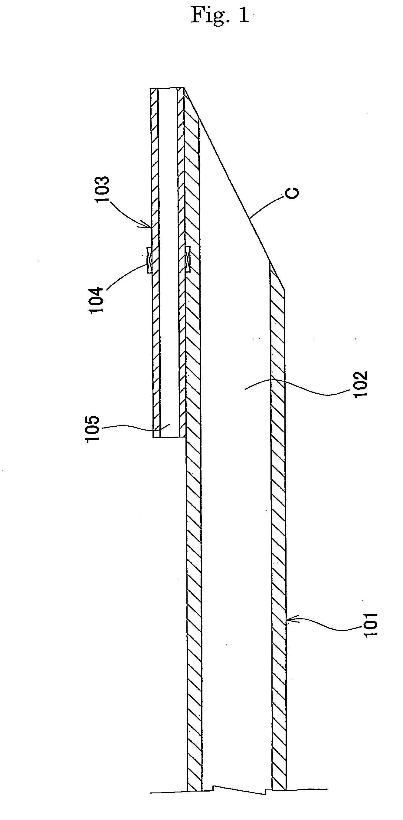
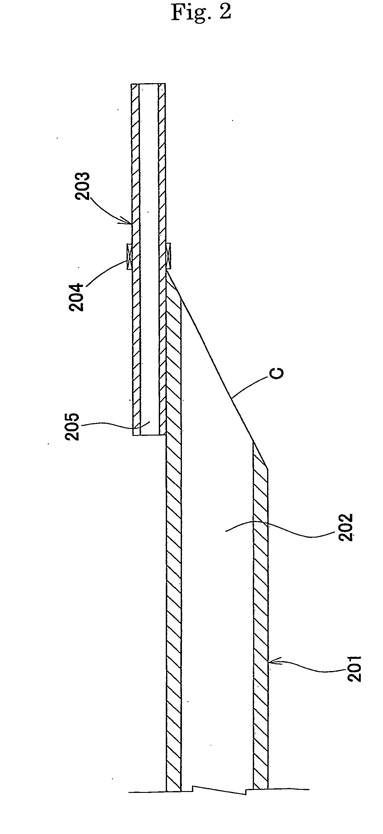
[0030] In the catheter, in order to confirm the position of the tip of the catheter by radioscopy, the guidewire shaft (103, 203, 303, 403, or 503) is provided with a radiopaque marker (104, 204, 304, 404, or 504) for confirming the position of the tip of the aspiration catheter by radioscopy. If the radiopaque marker (104, 204, 304, 404, or 504) is provided on the main shaft (101, 201, 301, 401, or 501), the portion provided with the radiopaque marker becomes extremely rigid, resulting in a large decrease in the trackability of the entire catheter. Therefore, the radiopaque marker (104, 204, 304, 404, or 504) having a minimally required size is preferably provided on the guidewire shaft (103, 203, 303, 403, or 503).
[0031] The
advantage of the present invention is not particularly restricted by the method for attaching the radiopaque marker (104, 204, 304, 404, or 504). Namely, the radiopaque marker may be bonded using an adhesive or the like, physically fixed (by
swaging), or attached by any other method. In order to minimize damage to the inner wall of the blood vessel due to the radiopaque marker (104, 204, 304, 404, or 504), preferably, the radiopaque marker (104, 204, 304, 404, or 504) is fixed by
swaging and the difference in level between the guidewire shaft (103, 203, 303, 403, or 503) and the radiopaque marker (104, 204, 304, 404, or 504) is reduced as much as possible.
[0032] Furthermore, the radiopaque marker (104, 204, 304, 404, or 504) may be composed of any material that shows high
visibility under radioscopy. A
metal material, such as stainless steel, gold, or
platinum, is preferably used for the radiopaque marker. A
gold alloy, a
platinum alloy, or the like may also be used.
[0033] Furthermore, at least a proximal portion of the main shaft (101, 201, 301, 401, or 501) is preferably composed of a high-modulus material with a
flexural modulus of 1 GPa or more. By using the shaft composed of such a high-modulus material, power at the proximal end can be fully transmitted to the tip of the catheter, and in addition to the pushing force and the pulling force, the rotating force can be sufficiently transmitted to the tip.
[0034] The main shaft (101, 201, 301, 401, or 501) preferably includes two shafts, i.e., a proximal shaft and a distal shaft. The distal shaft is preferably composed of a material having a lower modulus compared with the proximal shaft. Preferred examples of the material for the distal shaft include polyolefins, polyamides, polyesters, polyurethanes,
polyolefin elastomers,
polyamide elastomers,
polyester elastomers, and
polyurethane elastomers. Preferred examples of the material for the proximal shaft include polyimides,
polyamide-imides, polyether
ether ketones, stainless steel, and
nickel-
titanium alloys. The method for bonding the distal shaft to the proximal shaft is not particularly limited, and a known method, such as
welding or adhesion, may be used. Preferably, the change in rigidity at the joint between the distal shaft and the proximal shaft is reduced so that rigidity continuously changes in the longitudinal direction of the aspiration catheter.

