Particulate detector
a technology of particle detection and detector, applied in the field of particle detection, can solve the problems of reducing the performance of the turbine, faulty components, and inability to detect the results of contaminated areas, and achieve the effects of easy control, low back scatter or sparkle, and intense sparkl
- Summary
- Abstract
- Description
- Claims
- Application Information
AI Technical Summary
Benefits of technology
Problems solved by technology
Method used
Image
Examples
example 1
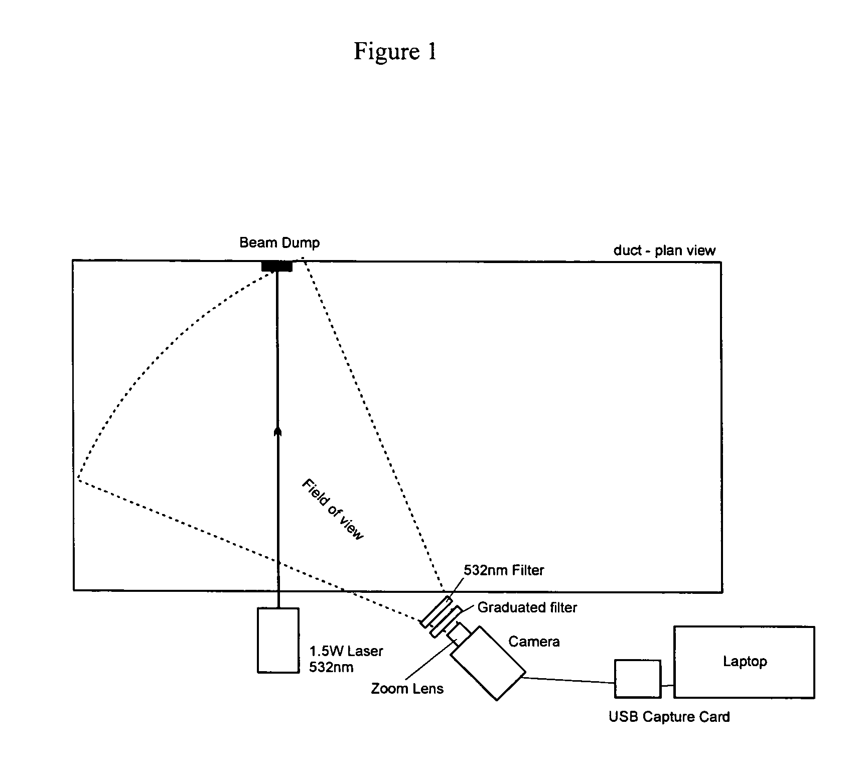
[0032]FIG. 1 is a plan view of an apparatus according to the invention is shown diagrammatically in which illumination is provided from an emitter 2 which is a laser having output 1.5 W, a beam width of about 2 mm, at a wavelength of 532 nm (green). The beam is fanned, using a cylindrical lens, across a duct 4 from one wall at approximately right angles to the beam wall, 50% of the cross section of the duct being illuminated. At the opposite wall, a beam dump 6 is provided to absorb illumination received at that point so that essentially no emitted light is reflected back from that wall. Sparkles from any particulate in the duct are detected by a 0.08 Lux C / CS mount CCD camera 8 having a 12 mm lens having the centre of its field of view about at an angle of 45° across the duct. The camera is fitted with a zoom lens 10 to focus the field of view, and with a 532 nm filter 12 so as to accept only sparkles caused by light from the emitter, and with a graduated neutral density filter 14 ...
example 2
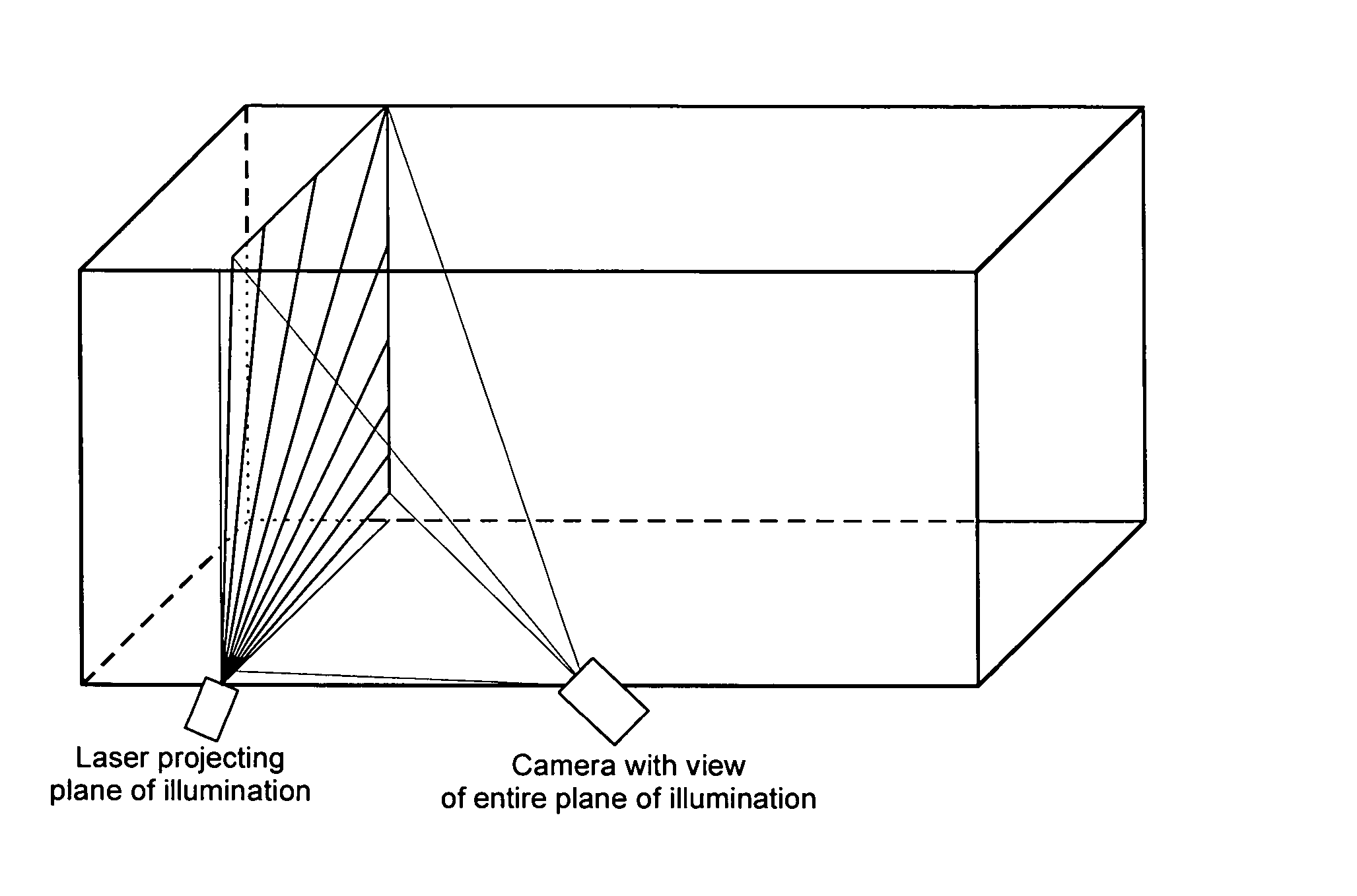
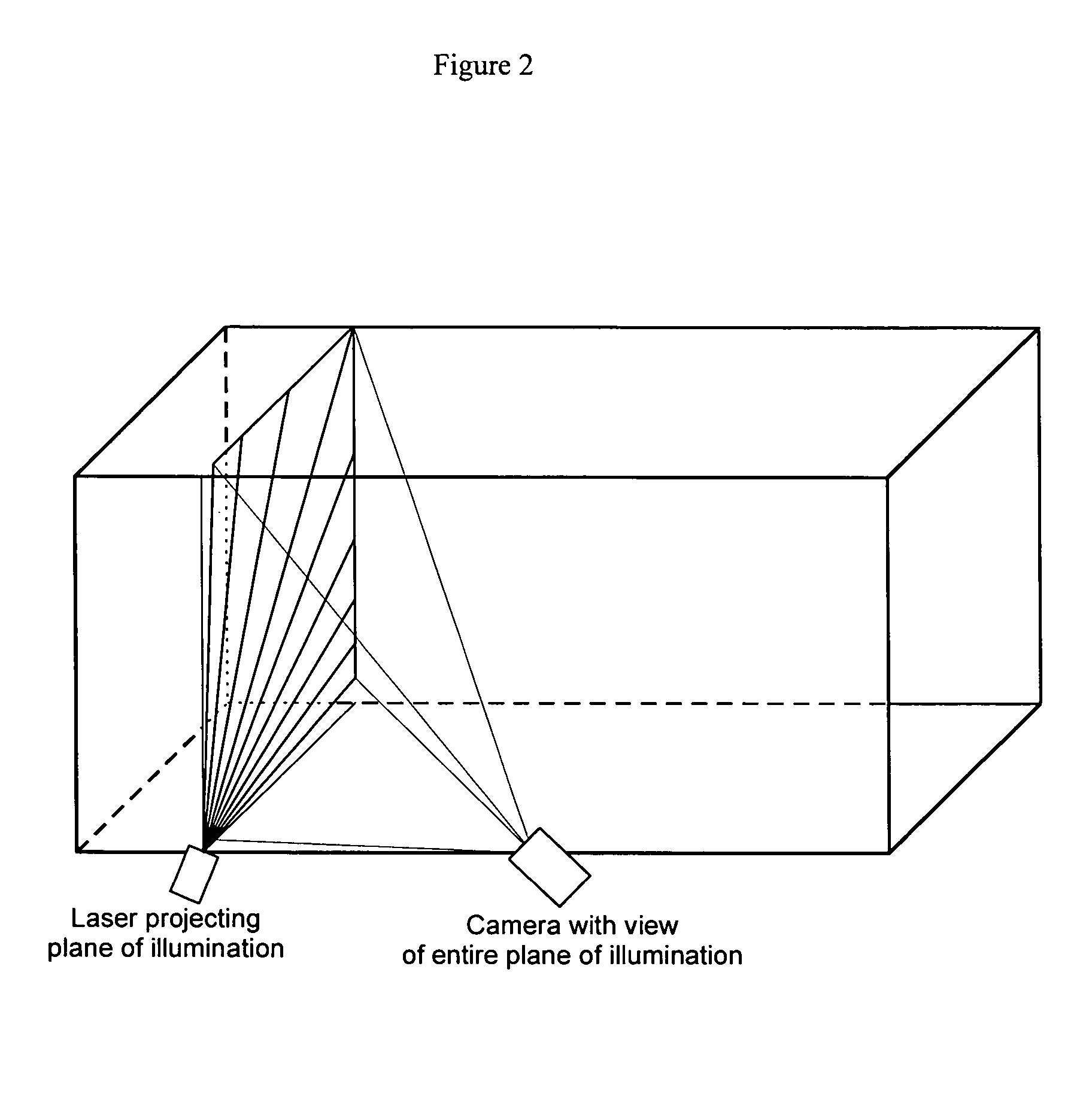
[0033]FIG. 2 is a 3-dimensional diagram of a illumination beam from the laser described in Example 1 in which the beam has been fanned using an optical lens across substantially the whole cross section of a duct; the emitter was positioned at a corner of the duct.
[0034] In a further embodiment of this apparatus, the beam from the laser is mechanically scanned using a stepper motor across substantially the whole cross section of the duct.
example 3
[0035]FIGS. 3 and 4 show diagrammatically an apparatus according to the invention in which back scatter is detected using illumination from a laser emitter having 3 mW output at wavelength 680 nm. The apparatus is mounted at right angles to the direction of gas flow. The illumination from the laser emitter is fanned using an optical line generator which spreads (i.e. fans) the beam in one plane through 80° so that 60% of the cross sectional area of the duct is illuminated. Back scatter is detected using four phototransistors 18 arranged as a square around the emitter 2. The output from the phototransistors is then amplified using high gain AC-coupled amplifiers 20 and summing amp 22 so that any effects of ambient light (including varying changing ambient light) are minimised, and so that only transient sparkles from passing particulate are captured.
[0036] In this embodiment of the apparatus of the invention, the PC stores information received from the amplifiers, and then calculate...
PUM
| Property | Measurement | Unit |
|---|---|---|
| wavelength | aaaaa | aaaaa |
| wavelength | aaaaa | aaaaa |
| inclusive angle | aaaaa | aaaaa |
Abstract
Description
Claims
Application Information
 - R&D
- Intellectual Property
- Life Sciences
- Materials
- Tech Scout
- Unparalleled Data Quality
- Higher Quality Content
- 60% Fewer Hallucinations
Browse by: Latest US Patents, China's latest patents, Technical Efficacy Thesaurus, Application Domain, Technology Topic, Popular Technical Reports.
© 2025 PatSnap. All rights reserved.Legal|Privacy policy|Modern Slavery Act Transparency Statement|Sitemap|About US| Contact US: help@patsnap.com


