
Method for producing recording medium, recording medium employing said method, and information recording and reproducing apparatus

a technology which is applied in the field of information recording and reproducing apparatus, can solve the problems of preventing accurate pattern transfer, difficult control of the shape or dimension of the micropattern obtained by processing, and not being realistic from the viewpoint of mass production, etc., to achieve accurate pattern transfer, facilitate the control of the processed shape or dimension, and high recording densities

Inactive Publication Date: 2005-12-01
HITACHI LTD
View PDF11 Cites 46 Cited by
  • Summary
  • Abstract
  • Description
  • Claims
  • Application Information

AI Technical Summary

Benefits of technology

[0020] It is therefore an object of the invention to provide a method of producing a low-cost recording medium with a high throughput for mass production in which the shape or dimensions of a pattern obtained by microfabrication can be easily controlled and which enables an accurate pattern transfer with superior uniformity. Another object of the invention is to provide a recording medium manufactured by the method and an information recording and reproducing apparatus utilizing the medium.
[0022] In accordance with the invention, a method for producing a magnetic recording medium is provided which is suitable for mass production, facilitates the control of the processed shape or dimensions, and enables an accurate pattern transfer. Using this method, a magnetic recording medium of high recording densities and a large-capacity magnetic disk unit can be provided.

Problems solved by technology

Although microfabrication on this order is possible with the electron beam lithography or reduction X-ray lithography technologies, the resultant throughput or price would not be realistic from the viewpoint of mass production.
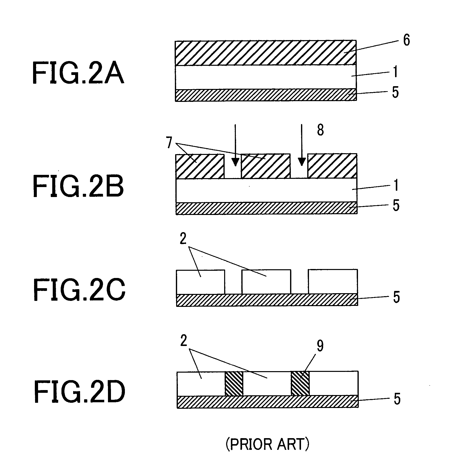
In this case, because the etching rate of the magnetic layer is low, the resist mask could be damaged, which would make it difficult to control the shape or dimensions of the micropattern obtained by processing.
There is also the problem in the imprint method in that, when transferring the pattern on the pattern mold onto the resist film, part of the resist could be transported to the pattern mold, thereby preventing an accurate pattern transfer.
In the microfabrication of a magnetic material using the RIE method, too, as in the case of the FIB process, the etching rate of the magnetic layer is low and the selectivity between the magnetic layer and the resist layer is poor, making it difficult to control the shape or dimensions of the processed micropattern.
When the self-organization of a block copolymer is utilized in JP Patent Publication (Kokai) No. 2002-359138 A, the structure of the block copolymer is limited, resulting in a low degree of freedom for forming an etch mask with a desired size at a desired position on the substrate.
Thus, there is the problem that it is difficult to control the shape or dimensions of the processed micropattern.
Because the arrangement or size of the dots is dependent on the beam forming conditions, it is difficult to arrange nanodots with a uniform size on the entire surface of a substrate in a dense manner.
Thus, it is difficult to control the shape or dimensions of the processed micropattern (nanodots).
The structure of the recent magnetic recording media is becoming increasingly more complex, with films of various compositions being layered to form a recording medium.
Therefore, it is difficult to embed a magnetic recording material with a complex film structure in all of the nanopores formed in the substrate in a uniform manner.

Method used


Image

  • Method for producing recording medium, recording medium employing said method, and information recording and reproducing apparatus
  • Method for producing recording medium, recording medium employing said method, and information recording and reproducing apparatus
  • Method for producing recording medium, recording medium employing said method, and information recording and reproducing apparatus

Examples


embodiment 1

[0051] Initially, a nano-particle as the material for a mask was prepared. Several processes are known for manufacturing nano-particles, of which a chemical synthetic process that will be described below is the most suitable for obtaining nano-particles with uniform grain size with a grain size distribution or 10% or less. A metal ion as a raw material was reduced in an organic solvent or an inorganic solvent containing water, thereby obtaining a metal atom. The metal atom, or a metal atom obtained by removing coordinate organic compounds around the metal atom, was then subjected to nucleus growth to obtain a metal nano-particle with a desired grain size. The metal ion or metal atom as the raw material may consist of a single element or a plurality of elements. When a plurality of elements are involved, an alloy nano-particle can be obtained. The grain size in the diameter range of 1 nm or greater and 100 nm or less can be controlled by optimizing factors such as the structure of th...

embodiment 2

[0058] An Au nano-particle single-layered film was formed on the entire surface of the magnetic layer by Langmuir-Blodgett (LB) process, instead of the spin coating process used Embodiment 1. In the present embodiment too, a solution of colloidal Au nano-particles with the diameter of 20 nm coated with dodecanethiol with the length of 4 nm was used.

[0059] In the following, a process of forming a nano-particle film by the LB process is described. The LB film is formed by adding the colloidal solution of metal nano-particles dropwise to clear water surface in a trough, thereby forming a single-layered film of nano-particles on the water surface. A movable barrier is then moved to slowly and gently compress the single-layered film floating on the water surface. Specifically, after washing the bottom, edges, and the movable barrier plate of the trough (water tank) of an LB film manufacturing apparatus with acetone, the trough was filled with ion-exchange water. The level of the water b...

embodiment 3

[0063] In Embodiments 1 and 2, the nano-particle film was formed on the entire surface of the magnetic layer. In Embodiment 3, an example is described in which the nano-particle film is partially formed on the magnetic layer. The soft magnetic layer, intermediate layer, and magnetic layer applied to the substrate were the same as those of Embodiments 1 and 2.

[0064]FIG. 11 shows a process for preparing the partial nano-particle film using a mold. Initially, a process of preparing a pattern transfer mold is described with reference to FIGS. 11A to 11D. Referring to FIG. 11A, a latent image of a desired micropattern is formed in a resist layer 28 formed on a molding substrate (such as that of SiN) 27, using EB lithography or optical lithography 29. The resist layer is then developed as shown in FIG. 11B, thereby exposing a micropattern 30 on the substrate of SiN or the like. The micropattern may be a concentric line-and-space pattern or it may be a lattice-shaped pattern such that con...


PUM

PropertyMeasurementUnit
grain size distributionaaaaaaaaaa
diameteraaaaaaaaaa
diameteraaaaaaaaaa

Abstract

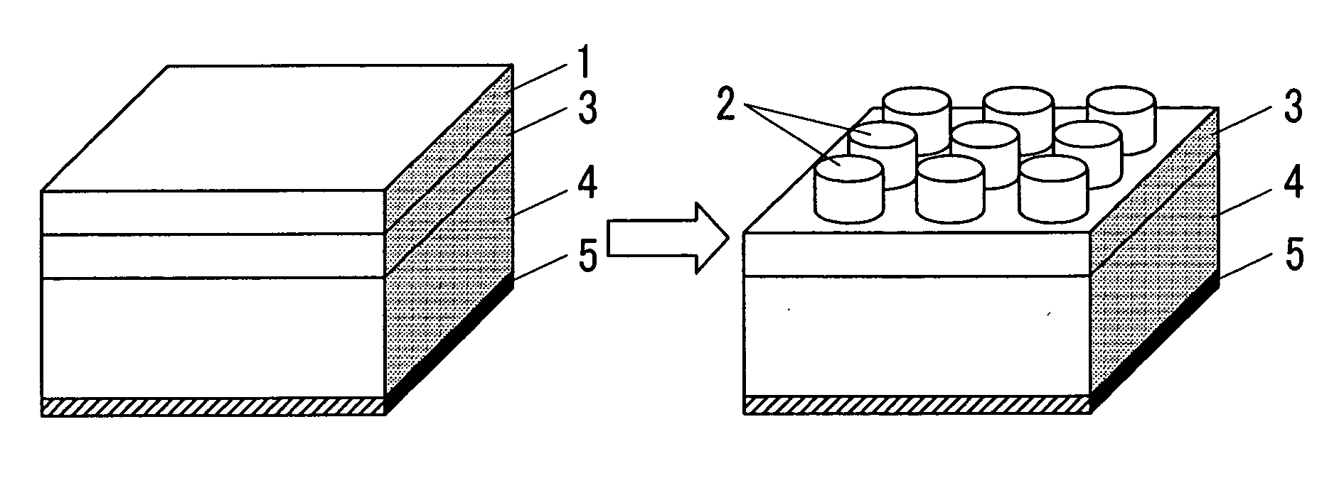
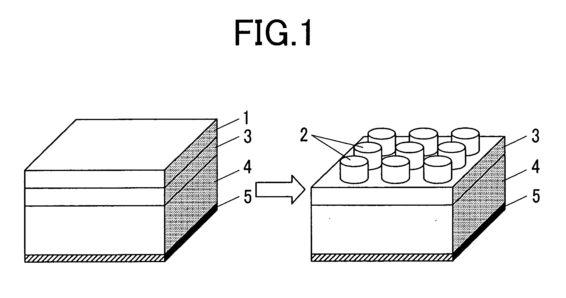
A method for producing a recording medium provides good throughput for mass production and reduces cost. The method facilitates the control of the shape or dimensions of a pattern obtained by microfabrication, allows an accurate pattern transfer, and provides superior uniformity. A magnetic layer is formed on a substrate. A nano-particle film 16 is formed on a desired portion on the magnetic layer. Using the nano-particle film as a mask, the magnetic layer is cut. A micropattern with concavities and convexities is formed on the magnetic layer by removing the nano-particle film.

Description

CLAIM OF PRIORITY [0001] The present application claims priority from Japanese application JP 2004-155005 filed on May 25, 2004, the content of which is hereby incorporated by reference into this application. BACKGROUND OF THE INVENTION [0002] 1. Field of the Invention [0003] The present invention relates to a method of manufacturing a magnetic recording medium or a thermomagnetic or optical-magnetic recording medium used in magnetic disk units or the like, and to an information recording and reproducing apparatus using these recording media. [0004] 2. Background Art [0005] In response to the increase in capacity of magnetic recording apparatus in recent years, efforts are being made to also increase the recording density of magnetic recording media. As the recording density increases, the single recording-bit size decreases, resulting in a pronounced superparamagnetic effect in which the magnetization on the magnetic recording film on the medium becomes thermally destabilized. As a...

Claims


Application Information

Patent Timeline
Patent Type & Authority Applications(United States)
IPC IPC(8): G11B5/02B05D5/12G11B5/00G11B5/33G11B5/84G11B5/855G11B11/105
CPCB82Y10/00G11B5/743G11B5/855G11B11/10528G11B11/10532Y10T428/11G11B11/10584G11B2005/0005G11B2005/0021G11B2005/0029G11B11/10582
Inventor TSUCHIYA, YUKOSOEYA, SUSUMUTAKAHASHI, HIROMASA
Owner HITACHI LTD
Learn More