This helps you quickly interpret patents by identifying the three key elements:
Problems solved by technology
Method used
Benefits of technology
[0110] Advantages of the present invention include, but not limited to, extended of hours of operability, operable capabilities beyond the conventional single slit spectral imaging systems, improved signal to noise rat
Problems solved by technology
Prior art imagers using a plurality of detectors at the image plane can exhibit serious signal-to-noise ratio problems.
Prior art imagers using a single element detector can exhibit more serious signal-to-noise ratio problems.
Signal-to-noise ratio problems limit the utility of imagers applied to chemical imaging applications where subtle differences between a sample's constituents become important.
However, the use of a plurality of detectors or the use of a macro moving grating has signal-to-noise limitations.
Each filter element employed can be very expensive, difficult to manufacture and all are permanently set at the time of manufacture in the wavelengths (bands) of radiation that they pass or reject.
Physical human handling of the filter elements can damage them and it is time consuming to change filter elements.
Clearly, however, this approach does not work in a more general case, and therefore it is desirable to have a controllable radiation source capable of providing arbitrary spectrum shapes and intensities.
A disadvantage of these systems is that they rely on an array of different LED elements (or lasers), each operating in a different, relatively narrow spectrum band.
In addition, there are technological problems associated with having an array of discrete radiation elements with different characteristics.
T
Method used
Image
Click on the blue label to locate the original text in one second.
Reading with bidirectional positioning of images and text.
Examples
Example
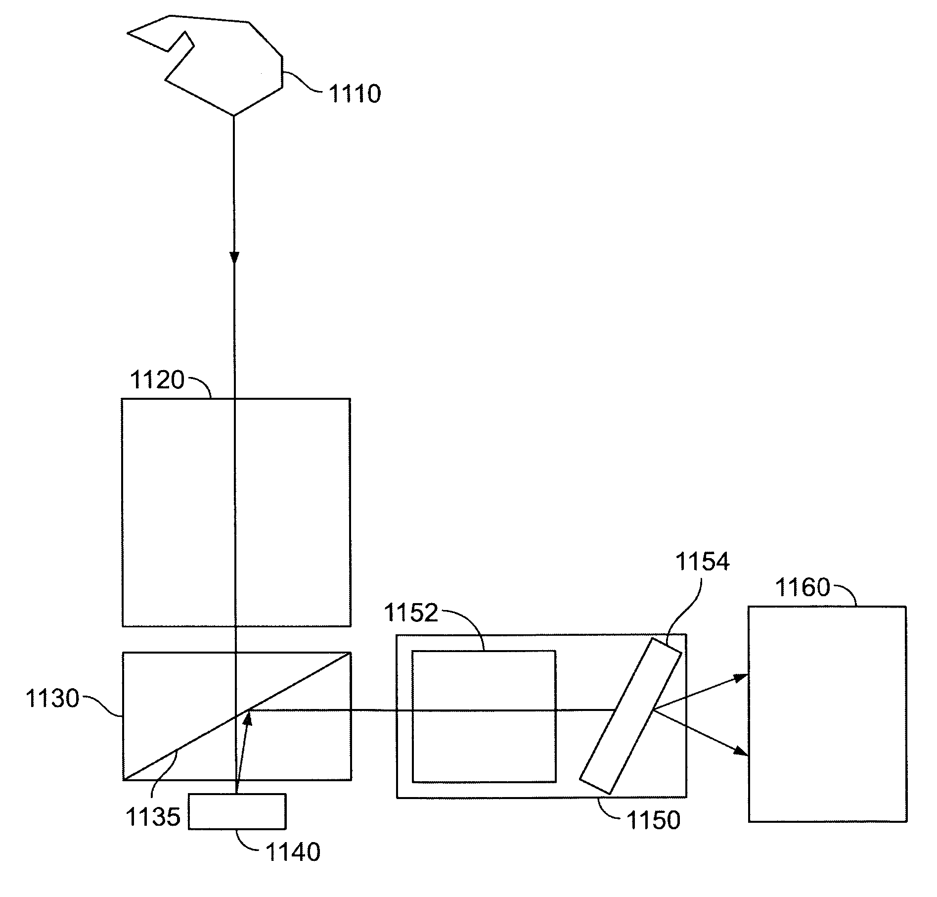
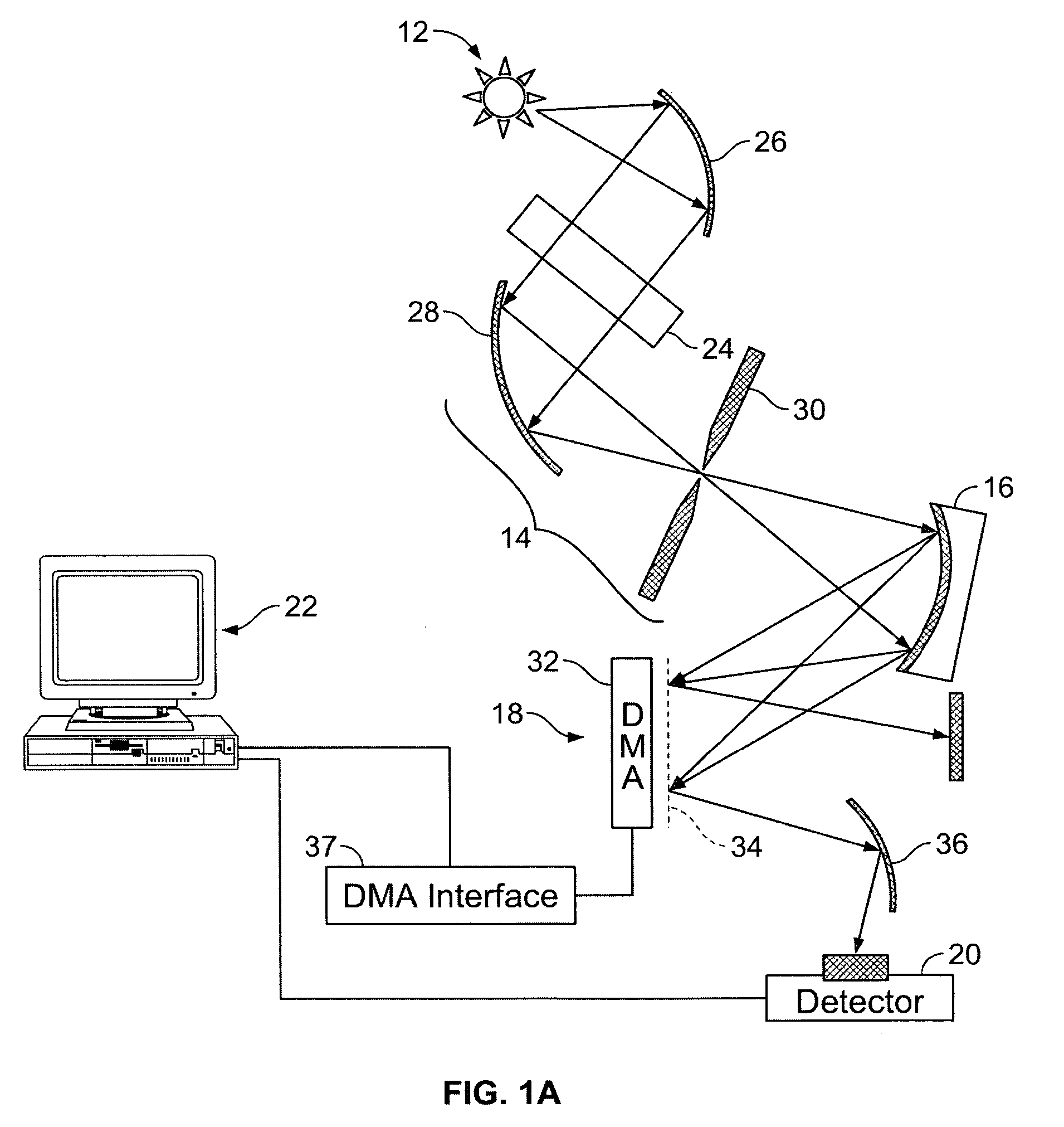
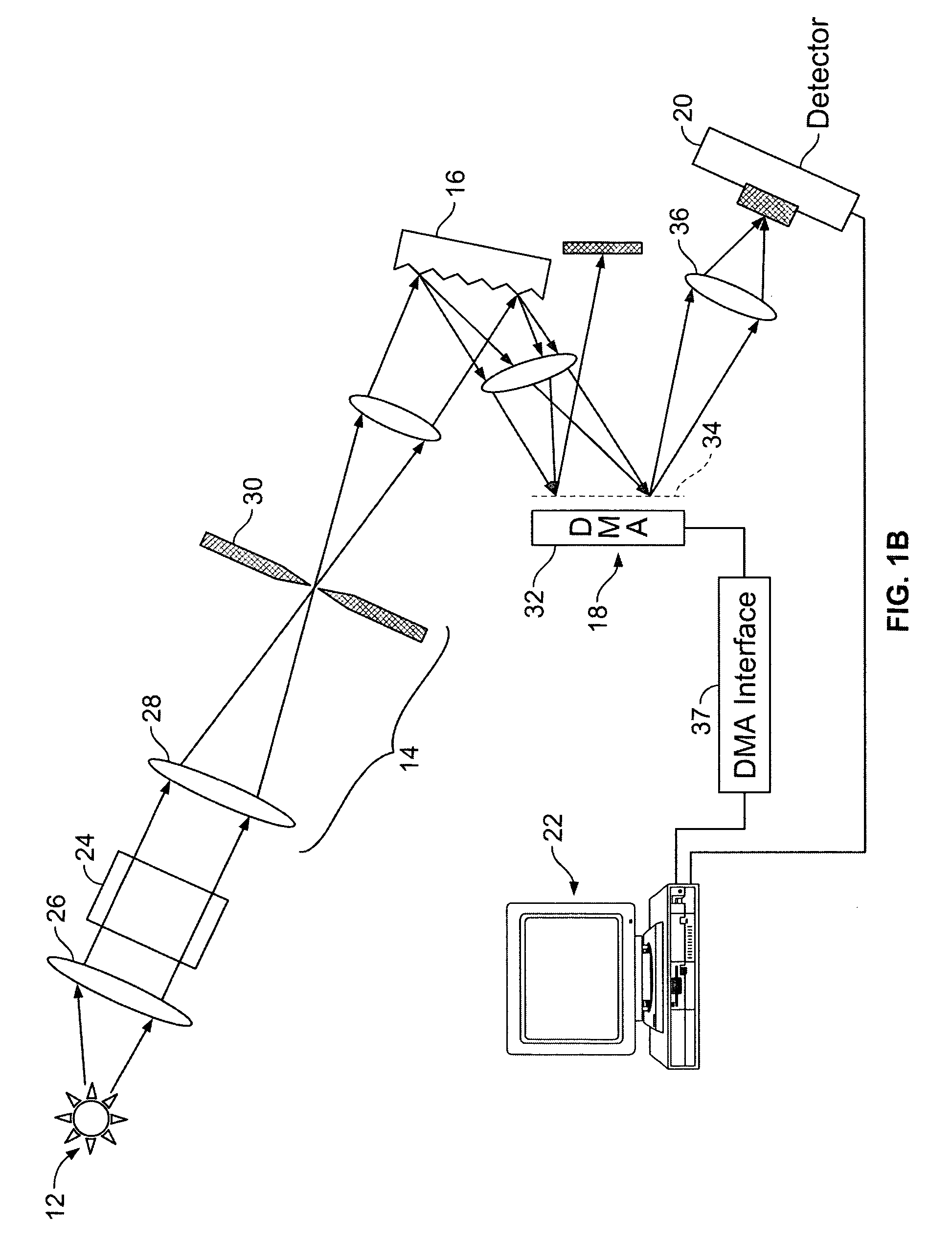
[0165] Turning now to the drawing figures and particularly FIGS. 1A and 1B, a spectrometer assembly 10 constructed in accordance with one embodiment of the invention is illustrated. With reference to FIG. 1A the device broadly includes a source 12 of electromagnetic radiation, a mirror and slit assembly 14, a wavelength dispersing device 16, a spatial light modulator 18, a detector 20, and an analyzing device 22.
[0166] In particular, the electromagnetic radiation source 12 is operable to project rays of radiation onto or through a sample 24 that is to be analyzed, such as a sample of body tissue or blood. The radiation source can be any device that generates electromagnetic radiation in a known wavelength spectrum such as a globar, hot wire, or light bulb that produces radiation in the infrared spectrum. To increase the amount of rays that are directed to the sample, a parabolic reflector 26 can be interposed between the source 12 and the sample 24. In a specific embodiment, the so...
PUM
Abstract
A hyper-spectral imaging system comprises imaging foreoptics to focus on a scene or object of interest and transfer the image of said scene or object onto the focal plane of a spatial light modulator, a spatial light modulator placed at a focal plane of said imaging foreoptics, an imaging dispersion device disposed to receive an output image of said spatial light modulator, and an image collecting device disposed to receive the output of said imaging dispersion device.
Description
RELATED APPLICATION [0001] This application claims priority benefit of provisional patent application No. 60 / 550,614, filed Mar. 6, 2004, which is incorporated by reference in its entirety and is a continuation-in-part of application Ser. No. 10 / 832,684, filed Apr. 26, 2004, which is a divisional of application Ser. No. 09 / 798,860, filed Mar. 1, 2001, now U.S. Pat. No. 6,859,275, which is a continuation-in-part of application Ser. No. 09 / 672,257, filed Sep. 28, 2000, now U.S. Pat. No. 6,392,748, which is a continuation of application Ser. No. 09 / 502,758 filed Feb. 11, 2000, now U.S. Pat. No. 6,128,078, which is a continuation of application Ser. No. 09 / 289,482 filed Apr. 9, 1999, now U.S. Pat. No. 6,046,808, each of which is incorporated by reference in its entirety.FIELD OF THE INVENTION [0002] The present invention relates generally to methods and devices for hyper-spectral imaging, more particularly to MEMS-modulated-aperture imaging spectrograph systems and methods. BACKGROUND O...
Claims
Application Information
Patent Timeline
Application Date:The date an application was filed.
Publication Date:The date a patent or application was officially published.
First Publication Date:The earliest publication date of a patent with the same application number.
Issue Date:Publication date of the patent grant document.
PCT Entry Date:The Entry date of PCT National Phase.
Estimated Expiry Date:The statutory expiry date of a patent right according to the Patent Law, and it is the longest term of protection that the patent right can achieve without the termination of the patent right due to other reasons(Term extension factor has been taken into account ).
Invalid Date:Actual expiry date is based on effective date or publication date of legal transaction data of invalid patent.